
Page 425 - Advanced thermodynamics for engineers
P. 425
17.4 COMBUSTION IN GAS TURBINES 415
50000
45000 T =1100K
max
T =1200K
max
T =1300K
max
T =1500K
Thrust, F /N T 35000
max
40000
30000
25000
1.0 1.2 1.4 1.6 1.8 2.0 2.2 2.4
Fan pressure ratio, r (-)
f
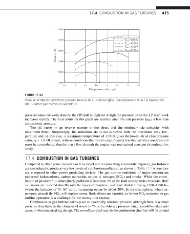
FIGURE 17.24
Variation of total thrust with fan pressure ratio (r f ) for a turbofan engine. Overall pressure ratio: 19; bypass ratio
(b): 3; (other parameters as Example 2).
pressure ratios the work done by the HP shaft is high but at high fan pressure ratios the LP shaft work
increases rapidly. The final points on this graph are reached when the exit pressure (p 06 ) is less than
atmospheric pressure.
The sfc varies in an inverse manner to the thrust and the minimum sfc coincides with
maximum thrust. Surprisingly, the minimum sfc is not achieved with the maximum peak tem-
perature and, in this case, a maximum temperature of 1100 K gives the lowest sfc at a fan pressure
ratio, r f ¼ 1.4. Of course, at these conditions the thrust is significantly less than at other conditions: it
must be remembered that the mass flow through the engine was maintained constant throughout this
study.
17.4 COMBUSTION IN GAS TURBINES
Compared to other prime movers (such as diesel and reciprocating automobile engines), gas turbines
are considered to produce very low levels of combustion pollution, as shown in Table 17.1 where they
are compared to other power producing devices. The gas turbine emissions of major concern are
unburned hydrocarbons, carbon monoxide, oxides of nitrogen (NO x ) and smoke. While the contri-
bution of jet aircraft to atmospheric pollution is less than 1% of the total atmospheric emissions, their
emissions are injected directly into the upper troposphere, and have doubled during 1970–1990 be-
tween the latitudes of 40–60 north, increasing ozone by about 20%. In the stratosphere, where su-
personic aircraft fly, NO x will deplete ozone. Both effects are harmful, so further NO x reduction in gas
turbine operation is a challenge for the twenty-first century.
Combustion in gas turbines takes place at essentially constant pressure, although there is a small
pressure drop through the chamber of about 5–7% of the delivery pressure which should be taken into
account when undertaking design. The overall air–fuel ratio in the combustion chamber will be around