
Page 420 - Advanced thermodynamics for engineers
P. 420
410 CHAPTER 17 GAS TURBINES
1
2 By-pass duct mb 5
Fan 6
3 8
Combustion 4
chambers
7
mt
mc
HP spool LP spool
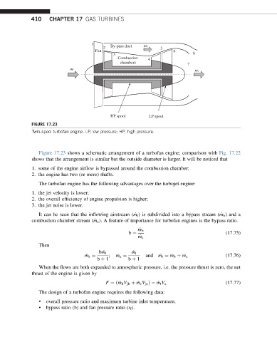
FIGURE 17.23
Twin-spool turbofan engine. LP, low pressure; HP, high pressure.
Figure 17.23 shows a schematic arrangement of a turbofan engine; comparison with Fig. 17.22
shows that the arrangement is similar but the outside diameter is larger. It will be noticed that
1. some of the engine airflow is bypassed around the combustion chamber;
2. the engine has two (or more) shafts.
The turbofan engine has the following advantages over the turbojet engine:
1. the jet velocity is lower;
2. the overall efficiency of engine propulsion is higher;
3. the jet noise is lower.
It can be seen that the inflowing airstream ( _ m t ) is subdivided into a bypass stream ( _ m b ) and a
combustion chamber stream ( _ m c ). A feature of importance for turbofan engines is the bypass ratio.
_ m b
b ¼ (17.75)
_ m c
Then
b _ m t _ m t
_ m b ¼ ; _ m c ¼ and _ m t ¼ _ m b þ _ m c (17.76)
b þ 1 b þ 1
When the flows are both expanded to atmospheric pressure, i.e. the pressure thrust is zero, the net
thrust of the engine is given by
F ¼ð _ m b V jb þ _ m c V jc Þ _ m t V a (17.77)
The design of a turbofan engine requires the following data:
• overall pressure ratio and maximum turbine inlet temperature;
• bypass ratio (b) and fan pressure ratio (r f ).