Page 416 - Advanced thermodynamics for engineers
P. 416

406    CHAPTER 17 GAS TURBINES


             and this is the same for both isentropic and irreversible adiabatic flows. Figure 17.19 shows that, while
             the critical value of T 04 /T c results in sonic flow at station 5, it is also necessary to evaluate T c , which is
             the temperature reached after isentropic expansion to p c , viz.
                                                      1
                                            T c0 ¼ T 04    ðT 04   T c Þ                 (17.71)
                                                      h j
             and then
                                               k       "              # k
                                                                        k 1
                                               k 1         1      T c
                                           T c0
                                  p c ¼ p 04      ¼ p 04 1     1                         (17.72)
                                          T 04             h j    T 04
                Hence
                                           p 04         1
                                              ¼              i k                         (17.73)
                                           p c  h    1 k   1  k 1

                                                 1    h j k þ 1
                The area of the nozzle can be evaluated from the mass flow rate required at the throat density and
             gas velocity. Then

                                                        _ m
                                                 A 5 ¼    ;                              (17.74)
                                                      r V c
                                                       c
                                                             1/2
             where r c ¼ p c /RT c and V c ¼ [2c p (T 04  T c )] 1/2  or (kRT c ) . The value obtained for A 5 will be
             approximate because there is a significant boundary layer built up in the nozzle which reduces the
             effective flow area. The value of h j achieved is dependent on the design of the particular nozzle, but a
             typical one might be 0.95.

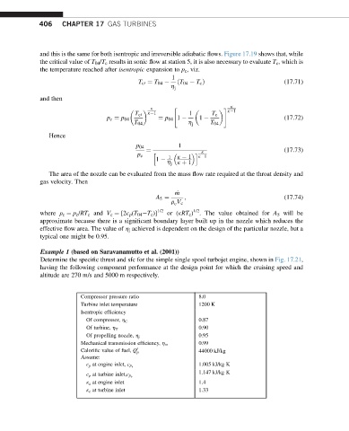
             Example 1 (based on Saravanamutto et al. (2001))
             Determine the specific thrust and sfc for the simple single spool turbojet engine, shown in Fig. 17.21,
             having the following component performance at the design point for which the cruising speed and
             altitude are 270 m/s and 5000 m respectively.


                          Compressor pressure ratio           8.0
                          Turbine inlet temperature           1200 K
                          Isentropic efficiency
                                                              0.87
                            Of compressor, h C
                                                              0.90
                            Of turbine, h T
                                                              0.95
                            Of propelling nozzle, h j
                                                              0.99
                          Mechanical transmission efficiency, h m
                          Calorific value of fuel, Q 0 p       44000 kJ/kg
                          Assume:
                                                              1.005 kJ/kg K
                            c p at engine inlet, c p a
                                                              1.147 kJ/kg K
                            c p at turbine inlet,c p e
                            k a at engine inlet               1.4
                            k e at turbine inlet              1.33
   411   412   413   414   415   416   417   418   419   420   421