
Page 411 - Advanced thermodynamics for engineers
P. 411
17.3 AIRCRAFT GAS TURBINES 401
1=2
p 4 p 2
¼ (17.59)
p 1 p 1
Hence, the pressure ratio for most effective reheat equally splits the gas turbine pressure ratio. This
results in equal work from each part of the turbine. If ε s 1 then the situation changes and the pressure
ratio has to be evaluated iteratively. The pressure ratio can also be evaluated iteratively if T 3 s T 5 and
if the compression and expansion are not isentropic.
17.2.3.2 Optimum pressure ratio for intercooling of gas turbines
The T–s diagram for an intercooled cycle is shown in Fig. 17.16. This cycle can be analysed in a similar
way to the one with reheat to determine the optimum intermediate pressure for intercooling, p i ,in
Fig. 17.16. This analysis is included in the tutorials as a problem for the student.
17.3 AIRCRAFT GAS TURBINES
These come in a number of variants as listed below:
1. turbojet
2. turbofan engine
3. turboprop engines
17.3.1 TURBOJET ENGINES
The previous sections have concentrated on gas turbines which produce a net shaft power output. The
majority of turbines are probably used for aero applications: some of these produce shaft power to
rotate a propeller but most (at present) produce a jet of hot gas which is then used for propulsion.
Basically all aero engines operate by producing an airstream moving in the opposite direction to the
aircraft. A propeller driven aircraft is propelled forwards by a large diameter, slow speed ‘jet’ produced
by the propeller. A simple jet engine propels rearwards a small diameter, high-speed jet, whilst a
turbofan engine produces a larger diameter, slower speed jet. It is instructive to consider why these
different mechanisms are used in different applications.
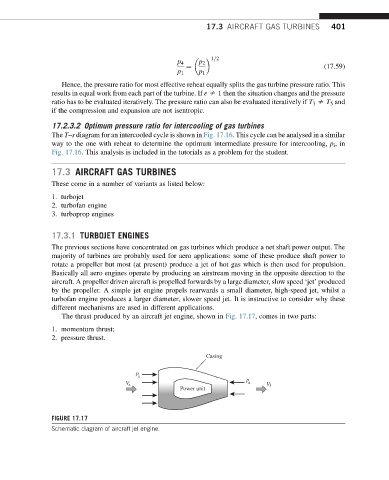
The thrust produced by an aircraft jet engine, shown in Fig. 17.17, comes in two parts:
1. momentum thrust;
2. pressure thrust.
Casing
p
a
p
V a a Vj
Power unit
FIGURE 17.17
Schematic diagram of aircraft jet engine.