
Page 415 - Advanced thermodynamics for engineers
P. 415
17.3 AIRCRAFT GAS TURBINES 405
engines which power supersonic aircraft: it is then often necessary to use variable area nozzles to limit
the shock losses produced in the nozzle itself. This section will concentrate on convergent nozzles only
because these are used on the majority of subsonic aircraft.
Two approaches can be used to define the performance of propelling nozzles:
1. isentropic efficiency, h j ;
2. specific thrust coefficient, K F .
This section will concentrate on the isentropic efficiency, h j . The nozzle diagram is given in
Fig. 17.19 and the value of h j is
T 04 T 5
h ¼ (17.69)
j
T 04 T 5
where T 04 is the stagnation temperature downstream of the turbine (see Figs 17.19 and 17.20).
It is then possible to evaluate the temperature drop across the nozzle, using the notation on
Fig. 17.19,as
k 1 #
"
1 k
T 04 T 5 ¼ h T 04 1 (17.70)
j
p 04 p 5
2
this is also equivalent to V =2c p , the kinetic energy term of the energy equation, because T 04 ¼ T 05 .
5
If the pressure ratio across the nozzle is less than the critical pressure ratio then the flow at the
nozzle exit is subsonic and the pressure at the exit plane of the nozzle equals the atmospheric pressure.
If the pressure ratio is greater than the critical one then full expansion of the gas will not occur in the
nozzle and the pressure at 5 will be greater than the ambient value. The critical pressure ratio, T 04 /T 05 ,
is one which results in M 5 ¼ 1. This is achieved when
T 04 k þ 1
¼ ðfrom the energy equationÞ;
T c 2
Combustion 3
Intake Compressor chamber Turbine Nozzle Temperature, T
a
1 2 3 4 5
4
5
2
1
a
Entropy, S
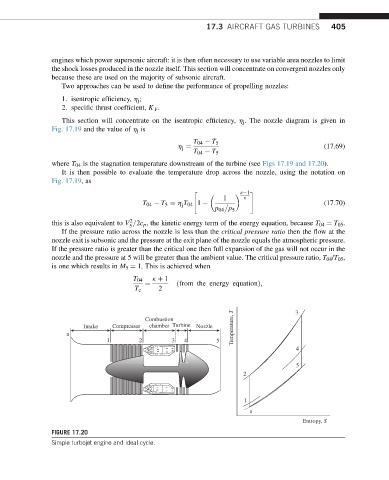
FIGURE 17.20
Simple turbojet engine and ideal cycle.