
Page 419 - Advanced thermodynamics for engineers
P. 419
17.3 AIRCRAFT GAS TURBINES 409
1 2 5
6
3
Combustion 4
chambers 7
m m
HP spool LP spool
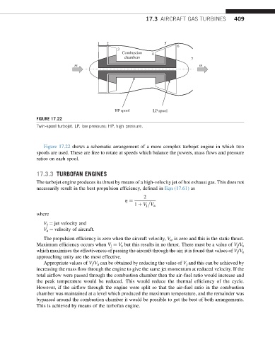
FIGURE 17.22
Twin-spool turbojet. LP, low pressure; HP, high pressure.
Figure 17.22 shows a schematic arrangement of a more complex turbojet engine in which two
spools are used. These are free to rotate at speeds which balance the powers, mass flows and pressure
ratios on each spool.
17.3.3 TURBOFAN ENGINES
The turbojet engine produces its thrust by means of a high-velocity jet of hot exhaust gas. This does not
necessarily result in the best propulsion efficiency, defined in Eqn (17.61) as
2
h ¼
1 þ V j V a
where
V j ¼ jet velocity and
V a ¼ velocity of aircraft.
The propulsion efficiency is zero when the aircraft velocity, V a , is zero and this is the static thrust.
Maximum efficiency occurs when V j ¼ V a but this results in no thrust. There must be a value of V j /V a
which maximises the effectiveness of passing the aircraft through the air; it is found that values of V j /V a
approaching unity are the most effective.
Appropriate values of V j /V a can be obtained by reducing the value of V j and this can be achieved by
increasing the mass flow through the engine to give the same jet momentum at reduced velocity. If the
total airflow were passed through the combustion chamber then the air–fuel ratio would increase and
the peak temperature would be reduced. This would reduce the thermal efficiency of the cycle.
However, if the airflow through the engine were split so that the air–fuel ratio in the combustion
chamber was maintained at a level which produced the maximum temperature, and the remainder was
bypassed around the combustion chamber it would be possible to get the best of both arrangements.
This is achieved by means of the turbofan engine.