
Page 408 - Advanced thermodynamics for engineers
P. 408
398 CHAPTER 17 GAS TURBINES
Maximum 3
temperature
Temperature, T
Q 1
2’ p 4
i
2
Q
Q 3
2
1’ 1
Intercooling
Entropy, S
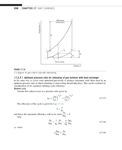
FIGURE 17.16
T–s diagram for gas turbine cycle with intercooling.
17.2.3.1 Optimum pressure ratio for reheating of gas turbines with heat exchange
In the same way as cycles were optimised previously to produce maximum work there must be an
optimum pressure ratio at which reheating or intercooling should take place. This can be evaluated by
consideration of the equations defining cycle efficiency.
Reheat cycle
Assume that reheat occurs at a pressure ratio given by
k 1 k 1
p R k p 4 k
s R ¼ ¼ (17.37)
p 1 p 1
The efficiency of the cycle is given by Eqn (17.4):
w
h ¼
q in
vh
and hence the maximum efficiency will occur when ¼ 0:
Now vs R
vh 1 vw w vq in
¼ 2 (17.38)
vs R q in vs R q vs R
in
i.e. when
vq in vw
h ¼ (17.39)
vs R vs R