
Page 528 - Advanced thermodynamics for engineers
P. 528
21.5 LOSSES IN FUEL CELLS 521
causing the theoretical voltage to fall linearly as current increases. It can be measured using a current
interrupt test, and can be reduced by lowering the resistance of the cell components.
21.5.4 MASS TRANSFER LOSSES
These mass transfer losses occur mainly when mixed fuels or oxidants are used, for example: air to
provide oxygen as the oxidant, or a hydrogen–carbon dioxide fuel mixture. Here there are gas
species that do not take an active part in the fuel cell reaction. At the surface of the PEM, the
hydrogen and oxygen are used up in the production of water. This reduces the concentration of the
fuel and oxidant gases at the active membrane surface. These depleted regions of hydrogen and
oxygen are replenished by diffusion of the reactant gases through the inactive species. The depleted
regions cause a reduction in the partial pressures of the hydrogen and oxygen. It can be shown, by
considering the Nernst equation, that pressure has an effect on the fuel cell voltage so mass transfer
or concentration losses can be modelled by the following equation (which takes negative values):
i
Voltage drop due to mass transfer; DV mass ¼ B ln 1 (21.65)
i l
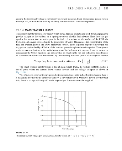
The effect of mass transfer losses is that at high current drains, the voltage suddenly reaches a
cut-off point where the current drawn cannot increase and the voltage collapses as shown in
Fig. 21.10.
This effect also occurs with pure gases due to pressure drops in the fuel cell system because there is
a maximum flow rate to the membrane surface. If the current drawn demands a greater flow rate than
this, then the voltage will drop off, as the required gas flow rate cannot be supplied.
1.2
V oltage, V / volts 1.0
0.8
0.6
0.4
0.2
0 1.0 2.0 3.0 4.0 5.0
Current, i / amps
FIGURE 21.10
Theoretical current-voltage plot showing mass transfer losses. [E ¼ 1.2 V, B ¼ 0.2 V, i l ¼ 4 A].