Page 526 - Advanced thermodynamics for engineers
P. 526

21.5 LOSSES IN FUEL CELLS       519


                                  1.0
                                               Measured
                                               voltage

                                              Modelled
                                              voltage
                               Voltage  0.5                         A


                                                                log i 0

                                  0.0
                                     1x10  -6    1x10 -5       1x10 -4        1x10 -3
                                                  logarithm of current (log i)
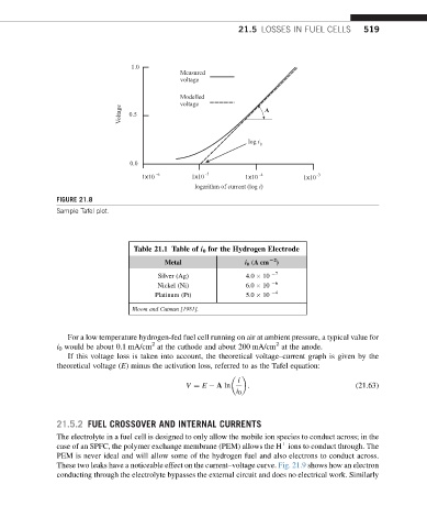
               FIGURE 21.8
               Sample Tafel plot.


                                   Table 21.1 Table of i 0 for the Hydrogen Electrode
                                           Metal               i 0 (A cm L2 )
                                         Silver (Ag)           4.0   10   7
                                         Nickel (Ni)           6.0   10   6
                                        Platinum (Pt)          5.0   10   4
                                  Bloom and Cutman [1981].


                  For a low temperature hydrogen-fed fuel cell running on air at ambient pressure, a typical value for
                                       2
                                                                       2
               i 0 would be about 0.1 mA/cm at the cathode and about 200 mA/cm at the anode.
                  If this voltage loss is taken into account, the theoretical voltage–current graph is given by the
               theoretical voltage (E) minus the activation loss, referred to as the Tafel equation:

                                                             i
                                                V ¼ E   A ln   :                           (21.63)
                                                             i 0


               21.5.2 FUEL CROSSOVER AND INTERNAL CURRENTS
               The electrolyte in a fuel cell is designed to only allow the mobile ion species to conduct across; in the
               case of an SPFC, the polymer exchange membrane (PEM) allows the H ions to conduct through. The
                                                                        þ
               PEM is never ideal and will allow some of the hydrogen fuel and also electrons to conduct across.
               These two leaks have a noticeable effect on the current–voltage curve. Fig. 21.9 shows how an electron
               conducting through the electrolyte bypasses the external circuit and does no electrical work. Similarly
   521   522   523   524   525   526   527   528   529   530   531