
Page 67 - Advanced thermodynamics for engineers
P. 67
3.2 AIR-STANDARD CYCLES 51
Chapter 16, by means of an engine simulation program. The results of the simulation are presented in a
form that should be intelligible to the reader of this chapter, without having assimilated all necessary
theory to understand the detailed workings of the program.
In the previous sections, engines have been compared based on their efficiencies. Another way of
assessing the output of reciprocating engines is to compare them on the basis of mean effective
pressure (mep). The indicated mean effective pressure of an engine ðp Þ is defined as the average
i
(mean) pressure that would have to operate over the whole stroke (V S ¼ V 1 V 2 ) to give the same
work output as the actual cycle, i.e.
H
pdV
p ¼ (3.28)
i
V S
The concept of meps will be returned to in Chapter 16.
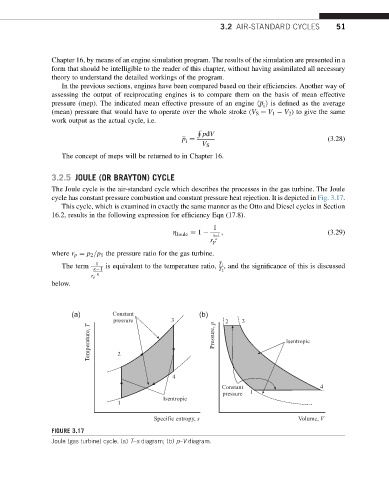
3.2.5 JOULE (OR BRAYTON) CYCLE
The Joule cycle is the air-standard cycle which describes the processes in the gas turbine. The Joule
cycle has constant pressure combustion and constant pressure heat rejection. It is depicted in Fig. 3.17.
This cycle, which is examined in exactly the same manner as the Otto and Diesel cycles in Section
16.2, results in the following expression for efficiency Eqn (17.8).
1
h Joule ¼ 1 k 1 ; (3.29)
k
r p
where r p ¼ p 2 =p 1 the pressure ratio for the gas turbine.
1
The term k 1 is equivalent to the temperature ratio, T 1 , and the significance of this is discussed
k T 2
r p
below.
(a) Constant (b)
pressure 3 2 3
Temperature, T 2 Pressure, p Isentropic
4
Constant 4
pressure 1
Isentropic
1
Specific entropy, s Volume, V
FIGURE 3.17
Joule (gas turbine) cycle. (a) T–s diagram; (b) p–V diagram.