
Page 63 - Advanced thermodynamics for engineers
P. 63
3.2 AIR-STANDARD CYCLES 47
(a) Constant (b)
volume 3 3
Temperature, T T a 2 Pressure, p Isentropic
_
Incremental
cycle
_ 4
T r 2 4
Isentropic Constant
1
volume 1
Specific entropy, s Volume, V
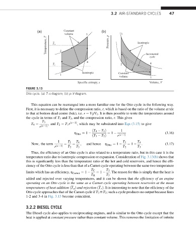
FIGURE 3.13
Otto cycle. (a) T–s diagram; (b) p–V diagram.
This equation can be rearranged into a more familiar one for the Otto cycle in the following way.
First, it is necessary to define the compression ratio, r, which is based on the ratio of the volume at tdc
to that at bottom dead centre (bdc), i.e. r ¼ V 2 /V 1 . It is then possible to write the temperatures around
the cycle in terms of T 1 and T 3 , and the compression ratio, r. This gives
T 3
T 4 ¼ ; and T 2 ¼ T 1 r ðk 1Þ , which may be substituted into Eqn (3.15) to give
r ðk 1Þ
ðT 4 T 1 Þ 1
h Otto ¼ 1 ¼ 1 (3.16)
ðT 3 T 2 Þ r ðk 1Þ
1 T 1 T 4 T 1 T 4
Now; the term ¼ ¼ ; and hence h Otto ¼ 1 ¼ 1 : (3.17)
r ðk 1Þ T 2 T 3 T 2 T 3
Thus, the efficiency of an Otto cycle is also related to a temperature ratio, but in this case it is the
temperature ratio due to isentropic compression or expansion. Consideration of Fig. 3.13(b) shows that
this is significantly less than the temperature ratio of the hot and cold reservoirs, and hence the effi-
ciency of the Otto cycle is less than that of a Carnot cycle operating between the same two temperature
T C T 1
limits which has an efficiency, h Carnot ¼ 1 ¼ 1 . The reason for this is simply that the heat is
T H T 3
added and rejected over varying temperatures, and it can be shown that the efficiency of an engine
operating on an Otto cycle is the same as a Carnot cycle operating between reservoirs at the mean
temperatures of heat addition ðT a Þ and rejection ðT r Þ. It is interesting to note that the efficiency of the
Otto cycle approaches that of the Carnot cycle if T 3 yT 2 ; such a cycle produces no output because lines
1-2 and 3-4 in Fig. 3.13 become coincident.
3.2.2 DIESEL CYCLE
The Diesel cycle also applies to reciprocating engines, and is similar to the Otto cycle except that the
heat is applied at constant pressure rather than constant volume. This removes the limitation of infinite