
Page 65 - Advanced thermodynamics for engineers
P. 65
3.2 AIR-STANDARD CYCLES 49
(a) (b) Constant
pressure
Constant 3 4 Incremental cycle
Temperature, T Constant 3 4 Pressure, p Isentropic
pressure
volume
2 2
5
5
Isentropic
1 V 2 V e Constant 1
volume
Specific entropy, s Volume, V
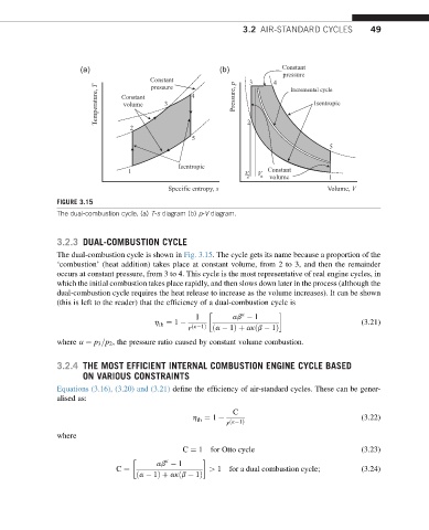
FIGURE 3.15
The dual-combustion cycle. (a) T-s diagram (b) p-V diagram.
3.2.3 DUAL-COMBUSTION CYCLE
The dual-combustion cycle is shown in Fig. 3.15. The cycle gets its name because a proportion of the
‘combustion’ (heat addition) takes place at constant volume, from 2 to 3, and then the remainder
occurs at constant pressure, from 3 to 4. This cycle is the most representative of real engine cycles, in
which the initial combustion takes place rapidly, and then slows down later in the process (although the
dual-combustion cycle requires the heat release to increase as the volume increases). It can be shown
(this is left to the reader) that the efficiency of a dual-combustion cycle is
k
1 ab 1
h ¼ 1 (3.21)
th
r ðk 1Þ ða 1Þþ akðb 1Þ
where a ¼ p 3 =p 2 , the pressure ratio caused by constant volume combustion.
3.2.4 THE MOST EFFICIENT INTERNAL COMBUSTION ENGINE CYCLE BASED
ON VARIOUS CONSTRAINTS
Equations (3.16), (3.20) and (3.21) define the efficiency of air-standard cycles. These can be gener-
alised as:
C
h ¼ 1 (3.22)
th
r ðk 1Þ
where
C ¼ 1 for Otto cycle (3.23)
k
ab 1
C ¼ > 1 for a dual combustion cycle; (3.24)
ða 1Þþ akðb 1Þ