
Page 59 - Advanced thermodynamics for engineers
P. 59
3.2 AIR-STANDARD CYCLES 43
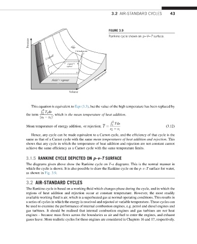
FIGURE 3.9
Rankine cycle shown on peVeT surface.
Pressure Gas
Critical point
5
Liquid
Solid 2 3 vapour 4
Liquid +
Temperature
1 1 6
Solid + vapour
Volume
This equation is equivalent to Eqn (3.3), but the value of the high temperature has been replaced by
R 5 T a ds
the term 2 , which is the mean temperature of heat addition.
ðs 5 s 2 Þ
2
R
1 Tds
Mean temperature of energy addition; or rejection; T ¼ (3.12)
s 2 s 1
Hence, any cycle can be made equivalent to a Carnot cycle, and the efficiency of that cycle is the
same as that of a Carnot cycle with the same mean temperatures of heat addition and rejection.This
shows that any cycle in which the temperature of heat addition and rejection are not constant cannot
achieve the same efficiency as a Carnot cycle with the same temperature limits.
3.1.5 RANKINE CYCLE DEPICTED ON p–v–T SURFACE
The diagrams given above show the Rankine cycle on T–s diagrams. This is the normal manner in
which the cycle is shown. It is also possible to draw the Rankine cycle on the p–v–T surface for water,
as shown in Fig. 3.9.
3.2 AIR-STANDARD CYCLES
The Rankine cycle is based on a working fluid which changes phase during the cycle, and in which the
regions of heat addition and rejection occur at constant temperature. However, the most readily
available working fluid is air, which is a superheated gas at normal operating conditions. This results in
a series of cycles in which the energy is received and rejected at variable temperature. These cycles can
be used to examine the performance of internal combustion engines, e.g. petrol and diesel engines and
gas turbines. It should be realised that internal combustion engines and gas turbines are not heat
engines – because mass flows across the boundaries as air and fuel to enter the engines, and exhaust
gases leave. More realistic cycles for these engines are considered in Chapters 16 and 17, respectively.