
Page 244 - Advances In Productive, Safe, and Responsible Coal Mining
P. 244
Engineered noise controls for miner safety and environmental responsibility 223
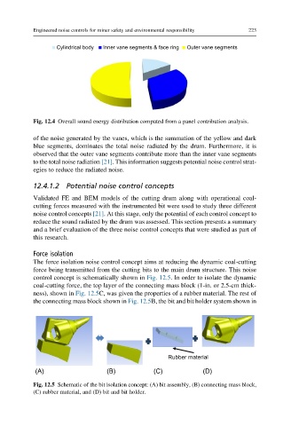
Cylindrical body Inner vane segments & face ring Outer vane segments
Fig. 12.4 Overall sound energy distribution computed from a panel contribution analysis.
of the noise generated by the vanes, which is the summation of the yellow and dark
blue segments, dominates the total noise radiated by the drum. Furthermore, it is
observed that the outer vane segments contribute more than the inner vane segments
to the total noise radiation [21]. This information suggests potential noise control strat-
egies to reduce the radiated noise.
12.4.1.2 Potential noise control concepts
Validated FE and BEM models of the cutting drum along with operational coal-
cutting forces measured with the instrumented bit were used to study three different
noise control concepts [21]. At this stage, only the potential of each control concept to
reduce the sound radiated by the drum was assessed. This section presents a summary
and a brief evaluation of the three noise control concepts that were studied as part of
this research.
Force isolation
The force isolation noise control concept aims at reducing the dynamic coal-cutting
force being transmitted from the cutting bits to the main drum structure. This noise
control concept is schematically shown in Fig. 12.5. In order to isolate the dynamic
coal-cutting force, the top layer of the connecting mass block (1-in. or 2.5-cm thick-
ness), shown in Fig. 12.5C, was given the properties of a rubber material. The rest of
the connecting mass block shown in Fig. 12.5B, the bit and bit holder system shown in
Rubber material
(A) (B) (C) (D)
Fig. 12.5 Schematic of the bit isolation concept: (A) bit assembly, (B) connecting mass block,
(C) rubber material, and (D) bit and bit holder.