
Page 253 - Advances In Productive, Safe, and Responsible Coal Mining
P. 253
232 Advances in Productive, Safe, and Responsible Coal Mining
(A) (B)
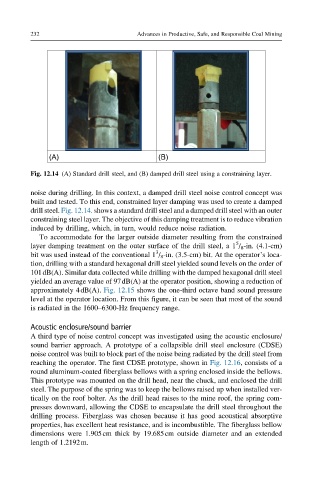
Fig. 12.14 (A) Standard drill steel, and (B) damped drill steel using a constraining layer.
noise during drilling. In this context, a damped drill steel noise control concept was
built and tested. To this end, constrained layer damping was used to create a damped
drill steel. Fig. 12.14. shows a standard drill steel and a damped drill steel with an outer
constraining steel layer. The objective of this damping treatment is to reduce vibration
induced by drilling, which, in turn, would reduce noise radiation.
To accommodate for the larger outside diameter resulting from the constrained
5
layer damping treatment on the outer surface of the drill steel, a 1 / 8 -in. (4.1-cm)
3
bit was used instead of the conventional 1 / 8 -in. (3.5-cm) bit. At the operator’s loca-
tion, drilling with a standard hexagonal drill steel yielded sound levels on the order of
101dB(A). Similar data collected while drilling with the damped hexagonal drill steel
yielded an average value of 97dB(A) at the operator position, showing a reduction of
approximately 4dB(A). Fig. 12.15 shows the one-third octave band sound pressure
level at the operator location. From this figure, it can be seen that most of the sound
is radiated in the 1600–6300-Hz frequency range.
Acoustic enclosure/sound barrier
A third type of noise control concept was investigated using the acoustic enclosure/
sound barrier approach. A prototype of a collapsible drill steel enclosure (CDSE)
noise control was built to block part of the noise being radiated by the drill steel from
reaching the operator. The first CDSE prototype, shown in Fig. 12.16, consists of a
round aluminum-coated fiberglass bellows with a spring enclosed inside the bellows.
This prototype was mounted on the drill head, near the chuck, and enclosed the drill
steel. The purpose of the spring was to keep the bellows raised up when installed ver-
tically on the roof bolter. As the drill head raises to the mine roof, the spring com-
presses downward, allowing the CDSE to encapsulate the drill steel throughout the
drilling process. Fiberglass was chosen because it has good acoustical absorptive
properties, has excellent heat resistance, and is incombustible. The fiberglass bellow
dimensions were 1.905cm thick by 19.685cm outside diameter and an extended
length of 1.2192m.