
Page 226 - Advances in Biomechanics and Tissue Regeneration
P. 226
222 11. ANALYSIS OF THE BIOMECHANICAL BEHAVIOR OF INTRAMEDULLARY NAILING
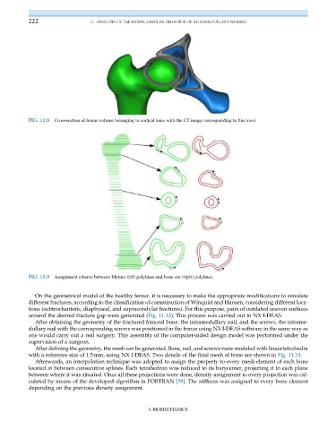
FIG. 11.8 Cross-section of femur volume belonging to cortical bone with the CT image corresponding to this level.
FIG. 11.9 Assignment scheme between Mimics (left) polylines and bone cut (right) polylines.
On the geometrical model of the healthy femur, it is necessary to make the appropriate modifications to simulate
different fractures, according to the classification of comminution of Winquist and Hansen, considering different loca-
tions (subtrochanteric, diaphyseal, and supracondylar fractures). For this purpose, pairs of outdated uneven surfaces
around the desired fracture gap were generated (Fig. 11.13). This process was carried out in NX I-DEAS.
After obtaining the geometry of the fractured femoral bone, the intramedullary nail, and the screws, the intrame-
dullary nail with the corresponding screws was positioned in the femur using NX I-DEAS software in the same way as
one would carry out a real surgery. This assembly of the computer-aided design model was performed under the
supervision of a surgeon.
After defining the geometry, the mesh can be generated. Bone, nail, and screws were modeled with linear tetrahedra
with a reference size of 1.5mm, using NX I-DEAS. Two details of the final mesh of bone are shown in Fig. 11.14.
Afterwards, an interpolation technique was adopted to assign the property to every mesh element of each bone
located in between consecutive splines. Each tetrahedron was reduced to its barycenter, projecting it to each plane
between where it was situated. Once all these projections were done, density assignment to every projection was cal-
culated by means of the developed algorithm in FORTRAN [39]. The stiffness was assigned to every bone element
depending on the previous density assignment.
I. BIOMECHANICS