
Page 229 - Advances in Biomechanics and Tissue Regeneration
P. 229
11.2 METHODOLOGY OF SIMULATION 225
FIG. 11.15 Perspective details of the fracture generated along with the homologous points to measure the micromovement (marked with dots).
Subsequently, in the fracture site, pairs of homologous points were determined (Fig. 11.15). These points, selected
from the mesh nodes located opposite to each other, will be used to measure the micromovements and identifying
trends in forming bone callus to the imposed loads. The model of the fractured femur was meshed according to
the previously described conditions.
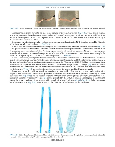
In the same way, the intramedullary nail and screws were meshed again using NX I-DEAS software. The FE model
of the intramedullary nail is shown in Fig. 11.16.
A linear tetrahedral was used to mesh the complete osteosynthesis model. The final FE model is shown in Fig. 11.17.
To guarantee the accuracy of the FE results, a sensitivity analysis was performed to determine the minimal mesh
size required for an accurate simulation. For this purpose, a mesh refinement was performed to achieve a convergence
toward a minimum of the potential energy, with a tolerance of 1% between consecutive meshes. As an example, the
statistics corresponding to one of the FE models are presented in Table 11.1.
In the FE simulation, the appropriate characterization of the mechanical behavior of the different materials, which is
usually very complex, is essential. Once the inner interface between the cortical and trabecular bone was determined in
the way explained before, material properties were assigned to the FE model in NX I-DEAS. They were assumed linear
elastic isotropic properties for the bone, with variable values related to the processed CT images [40]. The metallic nail
was made of 316 LVM steel or Ti-6L-4V and the metallic screws were made of 316 LVM steel, both assumed to be linear
elastic isotropic. Table 11.2 summarizes the mechanical properties values used in different materials.
Concerning the load conditions, a load case associated with an accidental support of the leg at early postoperative
stage has been considered. This load was quantified to be about 25% of the maximum gait load. According to Ortho-
load’s database (Fig. 11.18), the hip reaction force and abductor force, referring to 45% of the gait, corresponded to the
maximum and most representative load [42]. Forces generated by the abductor muscles were applied to the proximal
area of the greater trochanter, in agreement with most classic authors’ opinions [43, 44] (Fig. 11.19). Fully constrained
boundary conditions (Fig. 11.20) were applied at the distal part of each femur (at the condyles).
FIG. 11.16 Finite element model of the intramedullary nail: (A) front view of anterograde nail; (B) sagittal view of anterograde nail; (C) detail in
perspective of the head of the nail; (D) detail in perspective of the tip of the nail.
I. BIOMECHANICS