
Page 234 - Advances in Biomechanics and Tissue Regeneration
P. 234
230 11. ANALYSIS OF THE BIOMECHANICAL BEHAVIOR OF INTRAMEDULLARY NAILING
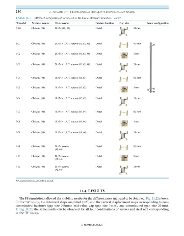
TABLE 11.3 Different Configurations Considered in the Finite Element Simulation—cont’d
FE model Proximal screws Distal screws Fracture location Gap size Screw configuration
A-09 Oblique (#1) 2L/M (#2, #3) Distal 20mm
B-01 Oblique (#1) 2L/M+1 A/P screws (#2, #3, #4) Distal 0.5mm
B-02 Oblique (#1) 2L/M+1 A/P screws (#2, #3, #4) Distal 3mm
B-03 Oblique (#1) 2L/M+1 A/P screws (#2, #3, #4) Distal 20mm
B-04 Oblique (#1) 1L/M+1 A/P screws (#2, #3) Distal 0.5mm
B-05 Oblique (#1) 1L/M+1 A/P screws (#2, #3) Distal 3mm
B-06 Oblique (#1) 1L/M+1 A/P screws (#2, #3) Distal 20mm
B-07 Oblique (#1) 1L/M+1 A/P screws (#3, #4) Distal 0.5mm
B-08 Oblique (#1) 1L/M+1 A/P screws (#3, #4) Distal 3mm
B-09 Oblique (#1) 1L/M+1 A/P screws (#3, #4) Distal 20mm
B-10 Oblique (#1) 2L/M screws Distal 0.5mm
(#2, #4)
B-11 Oblique (#1) 2L/M screws Distal 3mm
(#2, #4)
B-12 Oblique (#1) 2L/M screws Distal 20mm
(#2, #4)
A/P, anteroposterior; L/M, lateral-medial.
11.4 RESULTS
The FE simulations allowed the mobility results for the different cases analyzed to be obtained. Fig. 11.22 shows,
for the “A” study, the deformed shape amplified ( 25) and the vertical displacement maps corresponding to non-
comminuted fractures (gap size 0.5mm), mid-value gap (gap size 3mm), and comminuted (gap size 20mm).
In Fig. 11.23, the same results can be observed for all four combinations of screws and steel nail corresponding
to the “B” study.
I. BIOMECHANICS