
Page 55 - Advances in Biomechanics and Tissue Regeneration
P. 55
3.4 SIMULATION METHODOLOGY 49
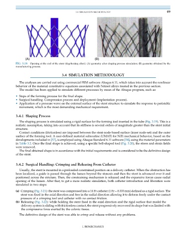
FIG. 3.18 Opening at the end of the stent (dog-boning effect): (A) geometry after shaping process simulation; (B) geometry obtained by the
manufacturing process.
3.4 SIMULATION METHODOLOGY
The analyses are carried out using commercial FEM software Abaqus 6.11, which takes into account the nonlinear
behavior of the material constitutive equations associated with Nitinol alloys treated in the previous section.
The model has been applied to simulate different processes by mean of the Abaqus program, such as:
• Steps of the forming process for the final shape.
• Surgical handling. Compression process and deployment (implantation process).
• Application of a pressure wave on the external surface of the stent structure to simulate the response to peristaltic
movement, which is the most demanding mechanical requirement.
3.4.1 Shaping Process
The shaping process is simulated using a rigid surface for the forming tool inserted in the tube (Fig. 3.19). This is a
realistic assumption, taking into account that its stiffness is several orders of magnitude greater than the stent initial
structure.
Contact conditions (frictionless) are imposed between the stent-node-based surface (inner node-set) and the outer
surface of the forming tool. A user-defined material subroutine (UMAT) for NiTi mechanical behavior, based on the
developments included in [57], is employed using Abaqus Standard 6.11 software [58], using the material parameters
in Table 3.2. Once the final shape is achieved, using a specific bell-shaped tool (Fig. 3.20), the stress and strain fields
were removed.
The final obtained shape is in accordance with the initial requirements and is considered to be the definitive design
of the stent.
3.4.2 Surgical Handling: Crimping and Releasing From Catheter
Usually, the stent is mounted in a preloaded constrained position on a delivery catheter. When the obstruction has
been localized, a guide is passed through the lumen beyond the stenosis and then the stent is advanced over it and
positioned across the stricture. Then, the constraining mechanism is released and the expansive forces cause radial
opening of the lumen. After that, to get a more realistic simulation, both catheter introduction and liberation were
simulated in two steps:
(a) Crimping (Fig. 3.21): the stent was compressed into a 14 Fr catheter (1 Fr¼0.333mm) defined as a rigid surface. The
stent was fixed in the axial direction and free in the radial direction allowing it to deform freely under the contact
pressure of a crimping tool and catheter with no contact friction.
(b) Releasing (Fig. 3.22): while holding the stent fixed in the axial direction and the rigid surface that model the
delivery system is sliding with frictionless contact, the stent progressively recovered its shape but was limited with
the compressive force exerted by the colonic tissue.
The definitive design of the stent was able to crimp and release without any problems.
I. BIOMECHANICS