
Page 160 - Advances in Eco-Fuels for a Sustainable Environment
P. 160
Microwave-assisted fast pyrolysis of hazardous waste engine oil into green fuels 131
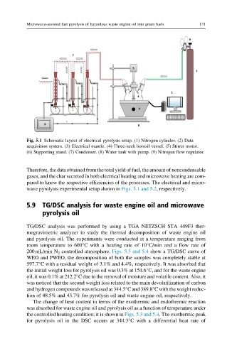
Fig. 5.1 Schematic layout of electrical pyrolysis setup. (1) Nitrogen cylinder. (2) Data
acquisition system. (3) Electrical mantle. (4) Three-neck borosil vessel. (5) Stirrer motor.
(6) Supporting stand. (7) Condenser. (8) Water tank with pump. (9) Nitrogen flow regulator.
Therefore, the data obtained from the total yield of fuel, the amount of noncondensable
gases, and the char secreted in both electrical heating and microwave heating are com-
pared to know the respective efficiencies of the processes. The electrical and micro-
wave pyrolysis experimental setup shown in Figs. 5.1 and 5.2, respectively.
5.9 TG/DSC analysis for waste engine oil and microwave
pyrolysis oil
TG/DSC analysis was performed by using a TGA NETZSCH STA 449F3 ther-
mogravimetric analyzer to study the thermal decomposition of waste engine oil
and pyrolysis oil. The experiments were conducted at a temperature ranging from
room temperature to 600°C with a heating rate of 10°C/min and a flow rate of
200mL/min N 2 controlled atmosphere. Figs. 5.3 and 5.4 show a TG/DSC curve of
WEO and PWEO, the decomposition of both the samples was completely stable at
597.7°C with a residual weight of 3.1% and 4.4%, respectively. It was absorbed that
the initial weight loss for pyrolysis oil was 0.3% at 154.6°C, and for the waste engine
oil, it was 0.1% at 212.2°C due to the removal of moisture and volatile content. Also, it
was noticed that the second weight loss related to the main devolatilization of carbon
and hydrogen compounds was released at 344.5°C and 389.8°C with the weight reduc-
tion of 48.5% and 43.7% for pyrolysis oil and waste engine oil, respectively.
The change of heat content in terms of the exothermic and endothermic reaction
was absorbed for waste engine oil and pyrolysis oil as a function of temperature under
the controlled heating condition; it is shown in Figs. 5.3 and 5.4. The exothermic peak
for pyrolysis oil in the DSC occurs at 344.3°C with a differential heat rate of