
Page 276 - Advances in Renewable Energies and Power Technologies
P. 276
6. Fault Detection Procedures 249
When some fault appears in the PV array, the output current and/or the output
voltage are reduced. The overall decrease in the output voltage depends on the num-
ber of short-circuited PV modules or the number of bypass diodes activated in the
PV modules that form the PV array. Moreover, the number of equivalent bypassed
modules, BPmod, present on the PV array is estimated as follows [41]:
NRv
BP mod ¼ Nsm 1 (7.46)
NRvo
On the other hand it is possible to estimate the equivalent number of faulty
strings, Efs, in the PV array when a decrease in output current is observed using
the following equation [41]:
NRc
Efs ¼ Npm 1 (7.47)
NRco
In normal operation of the PV system the values of the indicators NRc and NRv
should be very close to the values of NRco and NRvo given by Eqs. (40) and (41) and
maintain their values over specific thresholds. When one of the values of the indica-
tors, NRc or NRv, is below its defined threshold, TNRcfs and TNRvbm, Eqs. (42) and
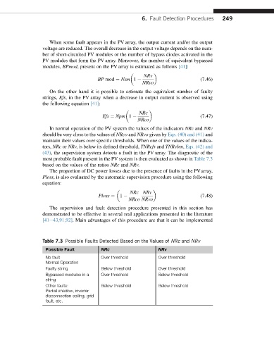
(43), the supervision system detects a fault in the PV array. The diagnostic of the
most probable fault present in the PV system is then evaluated as shown in Table 7.3
based on the values of the ratios NRc and NRv.
The proportion of DC power losses due to the presence of faults in the PV array,
Ploss, is also evaluated by the automatic supervision procedure using the following
equation:
NRc NRv
Ploss ¼ 1 (7.48)
NRco NRvo
The supervision and fault detection procedure presented in this section has
demonstrated to be effective in several real applications presented in the literature
[41e43,91,92]. Main advantages of this procedure are that it can be implemented
Table 7.3 Possible Faults Detected Based on the Values of NRc and NRv
Possible Fault NRc NRv
No fault Over threshold Over threshold
Normal Operation
Faulty string Below threshold Over threshold
Bypassed modules in a Over threshold Below threshold
string
Other faults: Below threshold Below threshold
Partial shadow, inverter
disconnection soiling, grid
fault, etc.