
Page 386 - Advances in Renewable Energies and Power Technologies
P. 386
3. Energy Management for Photovoltaic Installations 359
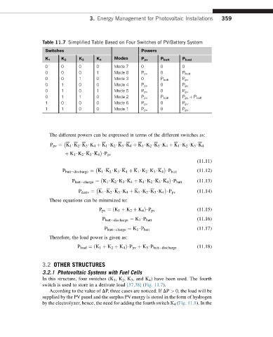
Table 11.7 Simplified Table Based on Four Switches of PV/Battery System
Switches Powers
Modes
K 1 K 2 K 3 K 4 P pv P batt P load
0 0 0 0 Mode 7 0 0 0
0 0 0 1 Mode 8 P pv 0 P batt
0 0 1 0 Mode 3 0 P batt P pv
0 1 0 0 Mode 4 P pv 0 P pv
0 1 0 1 Mode 5 P pv 0 P pv
0 1 1 0 Mode 2 P pv P batt P pv þ P batt
1 0 0 0 Mode 6 P pv 0 P pv
1 1 0 0 Mode 1 P pv 0 P pv
The different powers can be expressed in terms of the different switches as:
P pv ¼ K 1 $K 2 $K 3 $K 4 þ K 1 $K 2 $K 3 $K 4 þ K 1 $K 2 $K 3 $K 4 þ K 1 $K 2 $K 3 $K 4
þ K 1 $K 2 $K 3 $K 4 $P pv
(11.11)
P batt discharge ¼ K 1 $K 2 $K 3 $K 4 þ K 1 $K 2 $K 3 $K 4 $P batt (11.12)
P batt charge ¼ K 1 $K 2 $K 3 $K 4 þ K 1 $K 2 $K 3 $K 4 $P batt (11.13)
(11.14)
P deriv ¼ K 1 $K 2 $K 3 $K 4 þ K 1 $K 2 $K 3 $K 4 $P pv
These equations can be minimized to:
(11.15)
P pv ¼ðK 1 þ K 2 þ K 4 Þ$P pv
P batt discharge ¼ K 3 $P batt (11.16)
P batt charge ¼ K 1 $P batt (11.17)
Therefore, the load power is given as:
P load ¼ðK 1 þ K 2 þ K 4 Þ$P pv þ K 3 $P batt discharge (11.18)
3.2 OTHER STRUCTURES
3.2.1 Photovoltaic Systems with Fuel Cells
In this structure, four switches (K 1 ,K 2 ,K 3 , and K 4 ) have been used. The fourth
switch is used to store in a derivate load [37,38] (Fig. 11.7).
According to the value of DP, three cases are noticed. If DP > 0, the load will be
supplied by the PV panel and the surplus PVenergy is stored in the form of hydrogen
by the electrolyzer, hence, the need for adding the fourth switch K 4 (Fig. 11.8). In the