
Page 381 - Advances in Renewable Energies and Power Technologies
P. 381
354 CHAPTER 11 Energy Management for PV Installations
P pv, P load, SOC min, SOC max
Calculate P= P pv -P load
No Yes
P 0
SOC>SOC min
SOC< SOC max
No No Yes
Yes
Mode 5
P pv=0
Mode 4 Mode 1
No Yes
Mode 2 Mode 3
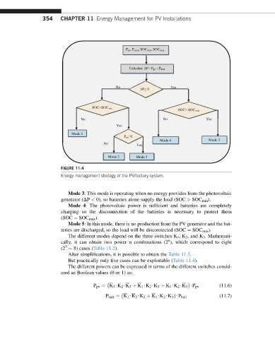
FIGURE 11.4
Energy management strategy of the PV/battery system.
Mode 3: This mode is operating when no energy provides from the photovoltaic
generator (DP < 0), so batteries alone supply the load (SOC > SOC min ).
Mode 4: The photovoltaic power is sufficient and batteries are completely
charging so the disconnection of the batteries is necessary to protect them
(SOC ¼ SOC max ).
Mode 5: In this mode, there is no production from the PV generator and the bat-
teries are discharged, so the load will be disconnected (SOC ¼ SOC min ).
The different modes depend on the three switches K 1 ,K 2 , and K 3 . Mathemati-
n
cally, it can obtain two power n combinations (2 ), which correspond to eight
3
(2 ¼ 8) cases (Table 11.2).
After simplifications, it is possible to obtain the Table 11.3.
But practically only five cases can be exploitable (Table 11.4).
The different powers can be expressed in terms of the different switches consid-
ered as Boolean values (0 or 1) as:
P pv ¼ K 1 $K 2 $K 3 þ K 1 $K 2 $K 3 þ K 1 $K 2 $K 3 $P pv (11.6)
(11.7)
P batt ¼ K 1 $K 2 $K 3 þ K 1 $K 2 $K 3 $P batt