
Page 380 - Advances in Renewable Energies and Power Technologies
P. 380
3. Energy Management for Photovoltaic Installations 353
3.1.1.1 First Structure of PMC
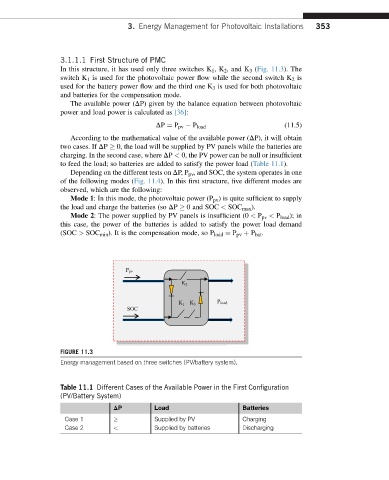
In this structure, it has used only three switches K 1 ,K 2 , and K 3 (Fig. 11.3). The
switch K 1 is used for the photovoltaic power flow while the second switch K 2 is
used for the battery power flow and the third one K 3 is used for both photovoltaic
and batteries for the compensation mode.
The available power (DP) given by the balance equation between photovoltaic
power and load power is calculated as [36]:
DP ¼ P pv P load (11.5)
According to the mathematical value of the available power (DP), it will obtain
two cases. If DP 0, the load will be supplied by PV panels while the batteries are
charging. In the second case, where DP < 0, the PV power can be null or insufficient
to feed the load; so batteries are added to satisfy the power load (Table 11.1).
Depending on the different tests on DP, P pv , and SOC, the system operates in one
of the following modes (Fig. 11.4). In this first structure, five different modes are
observed, which are the following:
Mode 1: In this mode, the photovoltaic power (P pv ) is quite sufficient to supply
the load and charge the batteries (so DP 0 and SOC < SOC max ).
Mode 2: The power supplied by PV panels is insufficient (0 < P pv < P load ); in
this case, the power of the batteries is added to satisfy the power load demand
(SOC > SOC min ). It is the compensation mode, so P load ¼ P pv þ P bat .
P pv
K 2
K 1 K 3 P load
SOC
FIGURE 11.3
Energy management based on three switches (PV/battery system).
Table 11.1 Different Cases of the Available Power in the First Configuration
(PV/Battery System)
DP Load Batteries
Case 1 Supplied by PV Charging
Case 2 < Supplied by batteries Discharging