
Page 379 - Advances in Renewable Energies and Power Technologies
P. 379
352 CHAPTER 11 Energy Management for PV Installations
The fill factor describes how square the I pv eV pv curve is. It is defined as
follows:
P pv max V pv max $I pv max
FF ¼ ¼ (11.3)
V oc $I sc V oc $I sc
where V oc and I sc are, respectively, the open-circuit voltage and short-circuit current.
So, the maximum efficiency can be expressed as:
FF$V oc $I sc
h pv max ¼ (11.4)
S pv $1000
The most efficient solar panels commercially available today have solar panel
efficiency just above 20%.
3. ENERGY MANAGEMENT FOR PHOTOVOLTAIC
INSTALLATIONS
3.1 PHOTOVOLTAIC SYSTEMS WITH STORAGE
3.1.1 Photovoltaic Systems with Battery Storage
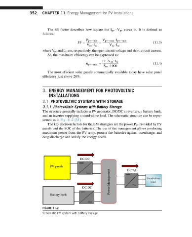
The structure generally includes a PV generator, DC/DC converters, a battery bank,
and an inverter supplying a stand-alone load. The schematic structure can be repre-
sented as in Fig. 11.2 [35].
The key decision factors for the EM strategies are the power P pv provided by PV
panels and the SOC of the batteries. The use of the management allows producing
maximum power from the PV array, protect the batteries against overcharge, and
deep discharge and satisfy the energy needs.
DC/DC
PV panels DC/AC
Power Management Stand-alone
load
DC/DC
Battery bank
FIGURE 11.2
Schematic PV system with battery storage.