
Page 391 - Advances in Renewable Energies and Power Technologies
P. 391
364 CHAPTER 11 Energy Management for PV Installations
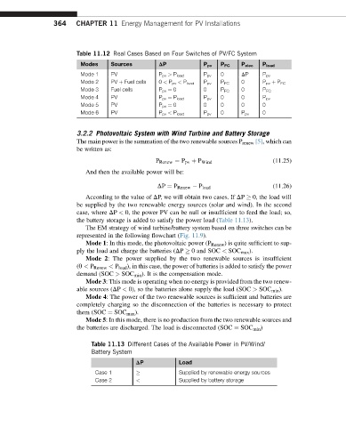
Table 11.12 Real Cases Based on Four Switches of PV/FC System
Modes Sources DP P pv P FC P elec P load
Mode 1 PV P pv > P load P pv 0 DP P pv
Mode 2 PV þ Fuel cells 0 < P pv < P load P pv P FC 0 P pv þ P FC
Mode 3 Fuel cells P pv ¼ 0 0 P FC 0 P FC
Mode 4 PV P pv ¼ P load P pv 0 0 P pv
Mode 5 PV P pv ¼ 0 0 0 0 0
Mode 6 PV P pv < P load P pv 0 P pv 0
3.2.2 Photovoltaic System with Wind Turbine and Battery Storage
The main power is the summation of the two renewable sources P renew [5], which can
be written as:
(11.25)
P Renew ¼ P pv þ P Wind
And then the available power will be:
DP ¼ P Renew P load (11.26)
According to the value of DP, we will obtain two cases. If DP 0, the load will
be supplied by the two renewable energy sources (solar and wind). In the second
case, where DP < 0, the power PV can be null or insufficient to feed the load; so,
the battery storage is added to satisfy the power load (Table 11.13).
The EM strategy of wind turbine/battery system based on three switches can be
represented in the following flowchart (Fig. 11.9).
Mode 1: In this mode, the photovoltaic power (P Renew ) is quite sufficient to sup-
ply the load and charge the batteries (DP 0 and SOC < SOC max ).
Mode 2: The power supplied by the two renewable sources is insufficient
(0 < P Renew < P load ), in this case, the power of batteries is added to satisfy the power
demand (SOC > SOC min ). It is the compensation mode.
Mode 3: This mode is operating when no energy is provided from the two renew-
able sources (DP < 0), so the batteries alone supply the load (SOC > SOC min ).
Mode 4: The power of the two renewable sources is sufficient and batteries are
completely charging so the disconnection of the batteries is necessary to protect
them (SOC ¼ SOC max ).
Mode 5: In this mode, there is no production from the two renewable sources and
the batteries are discharged. The load is disconnected (SOC ¼ SOC min )
Table 11.13 Different Cases of the Available Power in PV/Wind/
Battery System
DP Load
Case 1 Supplied by renewable energy sources
Case 2 < Supplied by battery storage