
Page 218 - Aerodynamics for Engineering Students
P. 218
Two-dimensional wing theory 201
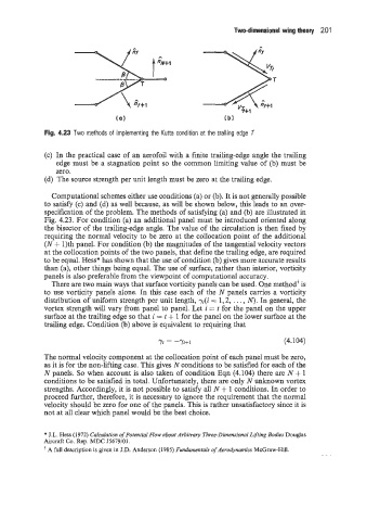
Fig. 4.23 Two methods of implementing the Kutta condition at the trailing edge T
(c) In the practical case of an aerofoil with a finite trailing-edge angle the trailing
edge must be a stagnation point so the common limiting value of (b) must be
zero.
(d) The source strength per unit length must be zero at the trailing edge.
Computational schemes either use conditions (a) or (b). It is not generally possible
to satisfy (c) and (d) as well because, as will be shown below, this leads to an over-
specification of the problem. The methods of satisfying (a) and (b) are illustrated in
Fig. 4.23. For condition (a) an additional panel must be introduced oriented along
the bisector of the trailing-edge angle. The value of the circulation is then fixed by
requiring the normal velocity to be zero at the collocation point of the additional
(N + 1)th panel. For condition (b) the magnitudes of the tangential velocity vectors
at the collocation points of the two panels, that define the trailing edge, are required
to be equal. Hess* has shown that the use of condition (b) gives more accurate results
than (a), other things being equal. The use of surface, rather than interior, vorticity
panels is also preferable from the viewpoint of computational accuracy.
There are two main ways that surface vorticity panels can be used. One method’ is
to use vorticity panels alone. In this case each of the N panels carries a vorticity
distribution of uniform strength per unit length, yi(i = 1,2, . . . , N>. In general, the
vortex strength will vary from panel to panel. Let i = t for the panel on the upper
surface at the trailing edge so that i = t + 1 for the panel on the lower surface at the
trailing edge. Condition (b) above is equivalent to requiring that
71 = -%+I (4.104)
The normal velocity component at the collocation point of each panel must be zero,
as it is for the non-lifting case. This gives N conditions to be satisfied for each of the
N panels. So when account is also taken of condition Eqn (4.104) there are N + 1
conditions to be satisfied in total. Unfortunately, there are only N unknown vortex
strengths. Accordingly, it is not possible to satisfy all N + 1 conditions. In order to
proceed further, therefore, it is necessary to ignore the requirement that the normal
velocity should be zero for one of the panels. This is rather unsatisfactory since it is
not at all clear which panel would be the best choice.
* J.L. Hess (1972) Calculation of Potential Flow about Arbitrary Three-Dimensional Lifting Bodies Douglas
Aircraft Co. Rep. MDC J5679,/01.
A full description is given in J.D. Anderson (1985) Fundamentals of Aerodynamics McGraw-Hill.