
Page 219 - Aerodynamics for Engineering Students
P. 219
202 Aerodynamics for Engineering Students
An alternative and more satisfactory method is to distribute both sources and
vortices of uniform strength per unit length over each panel. In this case, though, the
vortex strength is the same for all panels, i.e.
n=-y(i= 1,2, ..., N) (4.105)
Thus there are now N + 1 unknown quantities, namely the N source strengths and
the uniform vortex strength per unit length, 7, to match the N + 1 conditions. With
this approach it is perfectly feasible to use internal vortex panels instead of surface
ones. However these internal panels must carry vortices that are either of uniform
strength or of predetermined variable strength, providing the variation is character-
ized by a single unknown parameter. Generally, however, the use of surface vortex
panels leads to better results. Also Condition (a) can be used in place of (b). Again,
however, the use of Condition (b) generally gives more accurate results.
A practical panel method for lifting flows around aerofoils is described in some
detail below. This method uses Condition (b) and is based on a combination of
surface vortex panels of uniform strength and source panels. First, however, it is
necessary to show how the normal and tangential influence coefficients may be
evaluated for vortex panels. It turns out that the procedure is very similar to that
for source panels.
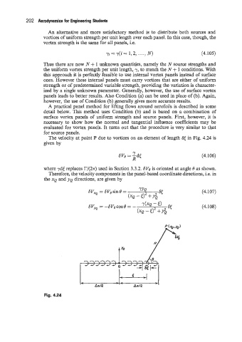
The velocity at point P due to vortices on an element of length S< in Fig. 4.24 is
given by
Y
SVe = -d< (4.106)
R
where ydc replaces r/(27r) used in Section 3.3.2. 6Ve is oriented at angle 8 as shown.
Therefore, the velocity components in the panel-based coordinate directions, i.e. in
the XQ and YQ directions, are given by
(4.107)
(4.108)
t yo
Fig. 4.24