
Page 278 - Aerodynamics for Engineering Students
P. 278
Finite wing theory 261
The pressure variation depicted in Fig. 5.38b has important consequences. First, if
it is borne in mind that suction pressure is plotted in Fig. 5.38, it can be seen that
there is a pronounced positive pressure gradient outward along the wing. This tends
to promote flow in the direction of the wing-tips which is highly undesirable.
Secondly, since the pressure distributions near the wing-tips are much peakier than
those further inboard, flow separation leading to wing stall tends to occur first near
the wing-tips. For straight wings, on the other hand, the opposite situation prevails
and stall usually first occurs near the wing root - a much safer state of affairs. The
difficulties briefly described above make the design of swept wings a considerably
more challenging affair compared to that of straight wings.
5.7.3 Wings of small aspect ratio
For the wings of large aspect ratio considered in Sections 5.5 and 5.6 above it was
assumed that the flow around each wing section is approximately two-dimensional.
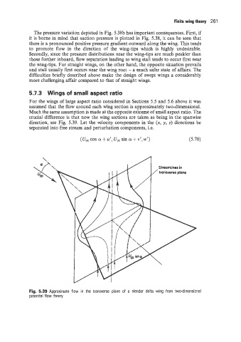
Much the same assumption is made at the opposite extreme of small aspect ratio. The
crucial difference is that now the wing sections are taken as being in the spanwise
direction: see Fig. 5.39. Let the velocity components in the (x, y, z) directions be
separated into free stream and perturbation components, i.e.
(U, cos a + u', U, sin a + v', w') (5.70)
streamlines in
/ transverse plane
Fig. 5.39 Approximate flow in the transverse plane of a slender delta wing from two-dimensional
potential flow theory