
Page 281 - Aerodynamics for Engineering Students
P. 281
264 Aerodynamics for Engineering Students
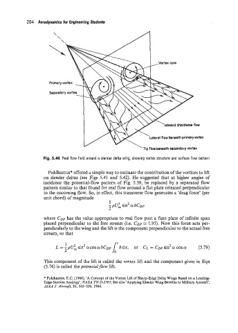
,Vortex core
Inboard chordwise flow
Lateral flow beneath primaryvortex
Tip flowbeneath secondary vortex
Fig. 5.40 Real flow field around a slender delta wing, showing vortex structure and surface flow pattern
Pohlhamus* offered a simple way to estimate the contribution of the vortices to lift
on slender deltas (see Figs 5.41 and 5.42). He suggested that at higher angles of
incidence the potential-flow pattern of Fig. 5.39, be replaced by a separated flow
pattern similar to that found for real flow around a flat plate oriented perpendicular
to the oncoming flow. So, in effect, this transverse flow generates a ‘drag force’ (per
unit chord) of magnitude
1
-pu; sin2 a bCDp
2
where CDP has the value appropriate to real flow past a flate plate of infinite span
placed perpendicular to the free stream (i.e. CDP 1.95). Now this force acts per-
pendicularly to the wing and the lift is the component perpendicular to the actual free
stream, so that
1
L = -pU; sin2 COS abC~p bdx, or CL = CDP sin2 a cos Q (5.79)
2
This component of the lift is called the vortex lift and the component given in Eqn
(5.76) is called the potentialflow lift.
* Pohlhamus, E.C. (1966), ‘A Concept of the Vortex Lift of Sharp-Edge Delta Wings Based on a Leading-
Edge-Suction Analogy’, NASA TN 0-3767; See also ‘Applying Slender Wing Benefits to Military Aircraft’,
AIAA J. Aircraft, 21, 545-559, 1984.