
Page 45 - Aerodynamics for Engineering Students
P. 45
28 Aerodynamics for Engineering Students
L Lift
Cross-wind
moment
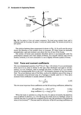
Fig. 1.8 The systems of force and moment components. The broad arrows represent forces used in
elementary work; the line arrows, the system in control and stability studies. The moments are common to
both systems
The relation between these components is shown in Fig. 1.8. In each case the arrow
shows the direction of the positive force or moment. All three forces are mutually
perpendicular, and each moment acts about the line of one of the forces.
The system of forces and moments described above is conventionally used for
performance analysis and other simple problems. For aircraft stability and control
studies, however, it is more convenient to use a slightly different system of forces.
I .5.2 Force and moment coefficients
The non-dimensional quantity F/(pV2S) (c.f. Eqn 1.43) (where Fis an aerodynamic
force and S is an area) is similar to the type often developed and used in aerody-
namics. It is not, however, used in precisely this form. In place of pV2 it is conven-
tional for incompressible flow to use ipVz, the dynamic pressure of the free-stream
flow. The actual physical area of the body, such as the planform area of the wing, or
the maximum cross-sectional area of a fuselage is usually used for S. Thus aero-
dynamic force coefficient is usually defined as follows:
F
CF = - (1.44)
ipV2s
The two most important force coefficients are the lift and drag coefficients, defined by:
lift coefficient CL = lift/ Jpv2S (1 .Ma)
drag coefficient CD = drag/ pV2S (1.44b)
When the body in question is a wing the area S is almost invariably the planform
area as defined in Section 1.3.1. For the drag of a body such as a fuselage, sphere or
cylinder the area S is usually the projected frontal area, the maximum cross-sectional
area or the The area used for definition of the lift and drag coefficients of