
Page 64 - Aerodynamics for Engineering Students
P. 64
Basic concepts and definitions 47
Effect of Reynolds number on the C,: a curve
Reduction of Reynolds number moves the transition point of the boundary layer
rearwards on the upper surface of the wing. At low values of Re this may permit
a laminar boundary layer to extend into the adverse pressure gradient region of the
aerofoil. As a laminar boundary layer is much less able than a turbulent boundary
layer to overcome an adverse pressure gradient, the flow will separate from the
surface at a lower angle of incidence. This causes a reduction of C,. This is a
problem that exists in model testing when it is always difficult to match full-scale and
model Reynolds numbers. Transition can be fixed artificially on the model by rough-
ening the model surface with carborundum powder at the calculated full-scale point.
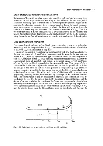
Drag coefficient: lift coefficient
For a two-dimensional wing at low Mach numbers the drag contains no induced or
wave drag, and the drag coefficient is CD,. There are two distinct forms of variation
of CD with CL, both illustrated in Fig. 1.26.
Curve (a) represents a typical conventional aerofoil with CD, fairly constant over
the working range of lift coefficient, increasing rapidly towards the two extreme
values of CL. Curve (b) represents the type of variation found for low-drag aerofoil
sections. Over much of the CL range the drag coefficient is rather larger than for the
conventional type of aerofoil, but within a restricted range of lift coefficient
(CL, to Cb) the profile drag coefficient is considerably less. This range of CL is
known as the favourable range for the section, and the low drag coefficient is due to
the design of the aerofoil section, which permits a comparatively large extent of
laminar boundary layer. It is for this reason that aerofoils of this type are also known
as laminar-flow sections. The width and depth of this favourable range or, more
graphically, low-drag bucket, is determined by the shape of the thickness distribu-
tion. The central value of the lift coefficient is known as the optimum or ideal lift
coefficient, Cbpt or C,. Its value is decided by the shape of the camber line, and the
degree of camber, and thus the position of the favourable range may be placed where
desired by suitable design of the camber line. The favourable range may be placed to
cover the most common range of lift coefficient for a particular aeroplane, e.g. Cb
may be slightly larger than the lift coefficient used on the climb, and CL, may be
0. -- -
Fig. 1.26 Typical variation of sectional drag coefficient with lift coefficient