
Page 231 - Aeronautical Engineer Data Book
P. 231
Airport design and compatibility 187
Shoulder
20 ft 317 ft
(96.6 m)
To
runway
40 ft 20 ft (6.1 m) clearance
(6.2 m) between centreline of gear
and pavement edge
Note
Before determining the size of the
intersection fillet, check with the
airlines regarding the operating
procedures that they use and the
aircraft types that are expected
to serve the airport
75ft (23 m)
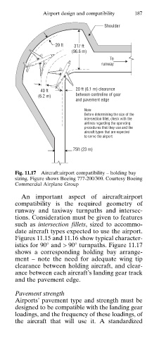
Fig. 11.17 Aircraft:airport compatibility – holding bay
sizing. Figure shows Boeing 777-200/300. Courtesy Boeing
Commercial Airplane Group
An important aspect of aircraft:airport
compatibility is the required geometry of
runway and taxiway turnpaths and intersec
tions. Consideration must be given to features
such as intersection fillets, sized to accommo
date aircraft types expected to use the airport.
Figures 11.15 and 11.16 show typical character
istics for 90° and > 90° turnpaths. Figure 11.17
shows a corresponding holding bay arrange
ment – note the need for adequate wing tip
clearance between holding aircraft, and clear
ance between each aircraft’s landing gear track
and the pavement edge.
Pavement strength
Airports’ pavement type and strength must be
designed to be compatible with the landing gear
loadings, and the frequency of these loadings, of
the aircraft that will use it. A standardized