
Page 228 - Aeronautical Engineer Data Book
P. 228
184 Aeronautical Engineer’s Data Book
45°
Main gear
centreline projection 50°
24 in (0.61 m) Nose gear axle
55° projection
Turning centre
(typical for steering 60°
angles shown)
Steering 65°
angle R1
R3 R2
R5
R6
R4
Notes:
• Data shown for airplane with aft axle steering
• Actual operating turning radii may be greater than shown.
• Consult with airline for specific operating procedure
• Dimensions rounded to nearest foot and 0.1 meter
Steering R1 R2 R3
angle Inner Outer Nose
gear gear gear
(Deg) Ft M Ft M Ft M
30 123 37.5 165 50.3 168 51.3
35 98 29.7 140 42.6 147 44.8
40 78 23.7 120 36.6 131 40.0
45 62 18.9 104 31.7 120 36.4
50 49 14.8 91 27.7 111 33.7
55 37 11.2 79 24.1 103 31.5
60 27 8.1 69 21.0 98 29.9
65 17 5.3 60 18.2 94 28.6
70 (max) 9 2.7 51 15.6 90 27.6
R4 R5 R6
Wing tip Nose Tail
Ft M Ft M Ft M
247 75.3 177 53.8 209 63.6
222 67.6 157 47.8 187 57.1
202 61.7 142 43.4 171 52.2
187 56.9 132 40.2 159 48.5
174 52.9 124 37.7 150 45.6
162 49.5 118 35.8 142 43.2
152 46.5 113 34.4 135 41.2
143 43.7 109 33.3 130 39.5
135 41.2 107 32.5 125 38.1
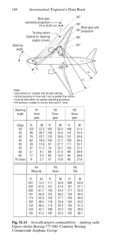
Fig. 11.13 Aircraft:airport compatibility – turning radii.
Figure shows Boeing 777-200. Courtesy Boeing
Commercial Airplane Group