
Page 229 - Aeronautical Engineer Data Book
P. 229
Airport design and compatibility 185
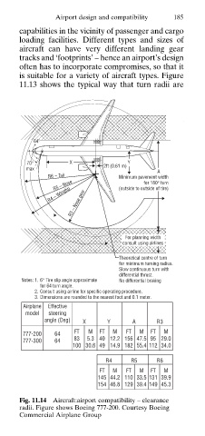
capabilities in the vicinity of passenger and cargo
loading facilities. Different types and sizes of
aircraft can have very different landing gear
tracks and ‘footprints’ – hence an airport’s design
often has to incorporate compromises, so that it
is suitable for a variety of aircraft types. Figure
11.13 shows the typical way that turn radii are
64°
70° X Y
max 2ft (0.61 m) A
R6 – Tail Minimum pavement width
R5 – Nose (outside to outside of tire)
for 180° turn
R4 – Wingtip
R3 – Nose gear
For planning width
consult using airlines
Theoretical centre of turn
for minimum turning radius.
Slow continuous turn with
differential thrust.
Notes: 1. 6° Tire slip angle approximate No differential braking
for 64 turn angle.
2. Consult using airline for specific operating procedure.
3. Dimensions are rounded to the nearest foot and 0.1 meter.
Airplane Effective
model steering
angle (Deg) X Y A R3
FT M FT M FT M FT M
777-200 64
777-300 64 83 5.3 40 12.2 156 47.5 95 29.0
100 30.6 49 14.9 182 55.4 112 34.0
R4 R5 R6
FT M FT M FT M
145 44.2 110 33.5 131 39.9
154 46.8 129 39.4 149 45.3
Fig. 11.14 Aircraft:airport compatibility – clearance
radii. Figure shows Boeing 777-200. Courtesy Boeing
Commercial Airplane Group