
Page 329 - Air Pollution Control Engineering
P. 329
06_chap_wang.qxd 05/05/2004 4:10 pm Page 308
308 Lawrence K. Wang et al.
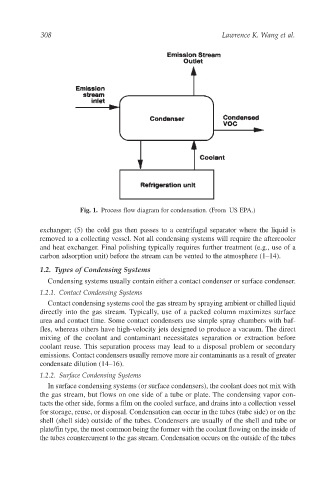
Fig. 1. Process flow diagram for condensation. (From US EPA.)
exchanger; (5) the cold gas then passes to a centrifugal separator where the liquid is
removed to a collecting vessel. Not all condensing systems will require the aftercooler
and heat exchanger. Final polishing typically requires further treatment (e.g., use of a
carbon adsorption unit) before the stream can be vented to the atmosphere (1–14).
1.2. Types of Condensing Systems
Condensing systems usually contain either a contact condenser or surface condenser.
1.2.1. Contact Condensing Systems
Contact condensing systems cool the gas stream by spraying ambient or chilled liquid
directly into the gas stream. Typically, use of a packed column maximizes surface
area and contact time. Some contact condensers use simple spray chambers with baf-
fles, whereas others have high-velocity jets designed to produce a vacuum. The direct
mixing of the coolant and contaminant necessitates separation or extraction before
coolant reuse. This separation process may lead to a disposal problem or secondary
emissions. Contact condensers usually remove more air contaminants as a result of greater
condensate dilution (14–16).
1.2.2. Surface Condensing Systems
In surface condensing systems (or surface condensers), the coolant does not mix with
the gas stream, but flows on one side of a tube or plate. The condensing vapor con-
tacts the other side, forms a film on the cooled surface, and drains into a collection vessel
for storage, reuse, or disposal. Condensation can occur in the tubes (tube side) or on the
shell (shell side) outside of the tubes. Condensers are usually of the shell and tube or
plate/fin type, the most common being the former with the coolant flowing on the inside of
the tubes countercurrent to the gas stream. Condensation occurs on the outside of the tubes