
Page 333 - Air Pollution Control Engineering
P. 333
06_chap_wang.qxd 05/05/2004 4:10 pm Page 312
312 Lawrence K. Wang et al.
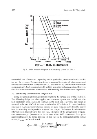
Fig. 4. Vapor pressure–temperature relationship. (From US EPA.)
on the shell side of the tubes. Depending on the application, the tube and shell side flu-
ids may be reversed. The emission stream is assumed to consist of a two-component
mixture: one condensible component (VOC, possible HAP), and one noncondensible
component (air). Such systems typically exhibit nonisothermal condensation. However,
the calculations here assume isothermality, which usually does not introduce large errors.
3.2. Estimating Condensation Temperature
Sizing the condenser involves steps to determine the surface area of the condenser.
The following design procedure applies to a condenser system with a shell and tube
heat exchanger, with condensate forming on the shell side. The waste gas stream is
assumed to be the VOC–air mixture noted earlier. Calculations for cases involving
mixtures of HAPs and supersaturated streams are quite complex and will not be treated
here because they are beyond the scope of this chapter. References 5 and 6 contain
information on these streams. For this case, estimation of the condensation tempera-
ture assumes the gas (air) stream to be saturated with a VOC component. For a given
removal efficiency, the partial pressure (in mm Hg) for the contaminant in the exiting
stream, P , can be calculated:
partial
(10. RE)
− 01
P partial = 760 −( − HAP ×10 −6 (1)
×
e
8
RE 10 HAP e)
1