
Page 47 - Air Pollution Control Engineering
P. 47
01_chap_wang.qxd 05/05/2004 11:46 am Page 27
Air Quality and Pollution Control 27
netic, but the particulate probes must be pointed directly into the gas flow and traverse
3
the entire duct. Usually, 5–10 min per traverse point are needed and at least 50 ft /min
of gas should be sampled. Two or more duplicate complete runs are desirable and may
be required for each system sampled.
6.7. Determination of Size Distribution
Normal size distribution has been discussed in Section 2, and a sample log probability
distribution plot is given in Fig. 1. It has been further pointed out that accurate size and
size distribution data are required in order to properly specify air pollution control
systems. It is difficult, however, to obtain accurate size data, especially when a large
portion of the particulates are fine (less than 3 µm).
Various size distribution techniques may be used, but the most accurate procedure for
fine particles is aerodynamic sizing, which consists of sizing the material in flight in the
duct. Methods for doing this include mechanical, optical, and condensation techniques
and a number of commercial sizing devices. The mechanical devices are rugged, highly
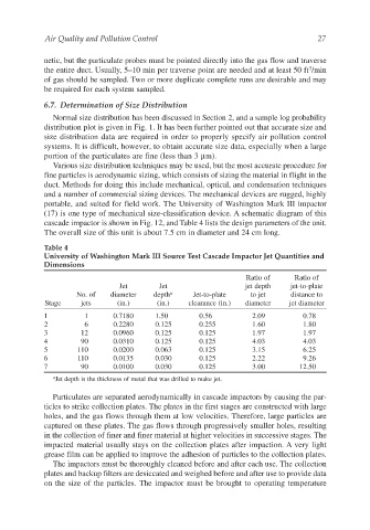
portable, and suited for field work. The University of Washington Mark III impactor
(17) is one type of mechanical size-classification device. A schematic diagram of this
cascade impactor is shown in Fig. 12, and Table 4 lists the design parameters of the unit.
The overall size of this unit is about 7.5 cm in diameter and 24 cm long.
Table 4
University of Washington Mark III Source Test Cascade Impactor Jet Quantities and
Dimensions
Ratio of Ratio of
Jet Jet jet depth jet-to-plate
No. of diameter depth a Jet-to-plate to jet distance to
Stage jets (in.) (in.) clearance (in.) diameter jet diameter
1 1 0.7180 1.50 0.56 2.09 0.78
2 6 0.2280 0.125 0.255 1.60 1.80
3 12 0.0960 0.125 0.125 1.97 1.97
4 90 0.0310 0.125 0.125 4.03 4.03
5 110 0.0200 0.063 0.125 3.15 6.25
6 110 0.0135 0.030 0.125 2.22 9.26
7 90 0.0100 0.030 0.125 3.00 12.50
a Jet depth is the thickness of metal that was drilled to make jet.
Particulates are separated aerodynamically in cascade impactors by causing the par-
ticles to strike collection plates. The plates in the first stages are constructed with large
holes, and the gas flows through them at low velocities. Therefore, large particles are
captured on these plates. The gas flows through progressively smaller holes, resulting
in the collection of finer and finer material at higher velocities in successive stages. The
impacted material usually stays on the collection plates after impaction. A very light
grease film can be applied to improve the adhesion of particles to the collection plates.
The impactors must be thoroughly cleaned before and after each use. The collection
plates and backup filters are desiccated and weighed before and after use to provide data
on the size of the particles. The impactor must be brought to operating temperature