
Page 569 - Air and Gas Drilling Manual
P. 569
Chapter 11: Specialized Drilling Equipment 11-7
table. When a course correction has been completed, the power swivel can be used
to rotate the drill string at a low speed (approximately 10 rpm or less). The slow
rotation of the drill string averages out the effect of the bent sub and allows straight
hole drilling. Under these drilling conditions, the rotating drill string stirs the rock
cutting off the low side of the borehole and more complete cleaning is accomplished.
But here again, periodic lifting of the drill string is usually necessary to eliminate
any cuttings accumulations. Here again, most conventional drill rig rotary tables
cannot rotate at speeds less than 30 rpm. Rotating at 30 rpm or greater with a bent
sub near the bottom of the drill string sharply increases the possibility of BHA
damage and a drill string mechanical failure which could result in a fishing job.
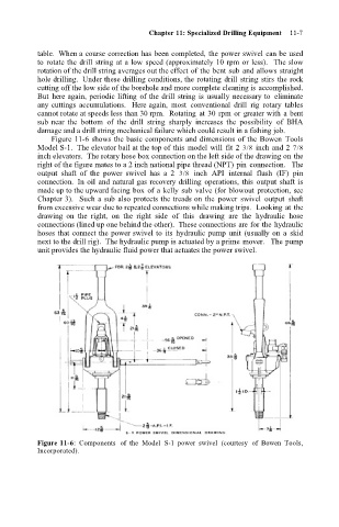
Figure 11-6 shows the basic components and dimensions of the Bowen Tools
Model S-1. The elevator bail at the top of this model will fit 2 3/8 inch and 2 7/8
inch elevators. The rotary hose box connection on the left side of the drawing on the
right of the figure mates to a 2 inch national pipe thread (NPT) pin connection. The
output shaft of the power swivel has a 2 3/8 inch API internal flush (IF) pin
connection. In oil and natural gas recovery drilling operations, this output shaft is
made up to the upward facing box of a kelly sub valve (for blowout protection, see
Chapter 3). Such a sub also protects the treads on the power swivel output shaft
from excessive wear due to repeated connections while making trips. Looking at the
drawing on the right, on the right side of this drawing are the hydraulic hose
connections (lined up one behind the other). These connections are for the hydraulic
hoses that connect the power swivel to its hydraulic pump unit (usually on a skid
next to the drill rig). The hydraulic pump is actuated by a prime mover. The pump
unit provides the hydraulic fluid power that actuates the power swivel.
Figure 11-6: Components of the Model S-1 power swivel (courtesy of Bowen Tools,
Incorporated).