
Page 193 - Air and gas Drilling Field Guide 3rd Edition
P. 193
184 CHAPTER 8 Air, Gas, and Unstable Foam Drilling
can later be used to control the drilling operation as the actual operation pro-
gresses. Air and gas drilling operations are different from traditional mud drilling
operations and require more intensive attention on the part of the on-site drilling
operation supervisor.
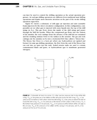
Figure 8-1 shows a schematic of drill pipe air injection and mist (unstable
foam) injection for the direct circulation configuration. In this configuration, com-
pressible air (or other gas) is injected with some liquids into the top of the drill
string (at P in ). This gas flows down the inside of the drill string and passes
through the drill bit nozzles. When the compressed gas flows into the bottom
of the annulus, the rock cuttings (from the advance of the drill bit) are entrained
and the resulting mixture flows to the surface in the annulus. The gas and rock
cuttings exit the annulus (at P e ) into a horizontal flow line called a “blooey line.”
The blooey line flows to a burn pit where any hydrocarbons are ignited and
burned. In some gas drilling operations, the flow from the end of the blooey line
can exit into an open top frac tank. Sealed returns tanks are used to contain
contaminated fluids and gases, or hydrocarbons (gas is membrane generated
nitrogen).
P (All)
P e in
P bca
P bdpi
P bdpa
P bdci
P bdca =P bh P ai
FIGURE 8-1. Schematic of direct circulation. P in is the injection pressure into the top of the drill
string, P bdpi is the pressure at the bottom of the drill pipe inside the drill string, P bdci is the
pressure at the bottom of drill collars inside the drill string, P ai is the pressure above the drill bit
inside the drill string, P bdca is the pressure at the bottom of drill collars in the annulus, P bh is
the bottom hole pressure in the annulus, P bdpa is the pressure at the bottom of the drill pipe in
the annulus, P bca is the pressure at the bottom of the casing in the annulus, and P e is the
pressure at the top of the annulus.