
Page 225 - Air and gas Drilling Field Guide 3rd Edition
P. 225
216 CHAPTER 9 Aerated Fluids Drilling
P (All)
in
P e
P bca
P bdpi
P bdpa
P bdci
P ai
P bdca =P bh
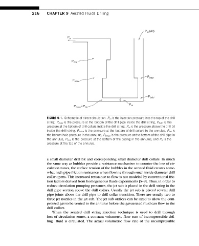
FIGURE 9-1. Schematic of direct circulation. P in is the injection pressure into the top of the drill
string, P bdpi is the pressure at the bottom of the drill pipe inside the drill string, P bdci is the
pressure at the bottom of drill collars inside the drill string, P ai is the pressure above the drill bit
inside the drill string, P bdca is the pressure at the bottom of drill collars in the annulus, P bh is
the bottom hole pressure in the annulus, P bdpa is the pressure at the bottom of the drill pipe in
the annulus, P bca is the pressure at the bottom of the casing in the annulus, and P e is the
pressure at the top of the annulus.
a small diameter drill bit and corresponding small diameter drill collars. In much
the same way as bubbles provide a resistance mechanism to counter the loss of cir-
culation zones, the surface tension of the bubbles in the aerated fluid creates some-
what high pipe friction resistance when flowing through small inside diameter drill
collar opens. This increased resistance to flow is not modeled by conventional fric-
tion factors derived from homogeneous fluids experiments [5–9]. Thus, in order to
reduce circulation pumping pressures, the jet sub is placed in the drill string in the
drill pipe section above the drill collars. Usually the jet sub is placed several drill
pipe joints above the drill pipe to drill collar transition. There are usually two to
three jet nozzles in the jet sub. The jet sub orifices can be sized to allow the com-
pressed gas to be vented to the annulus before the gas-aerated fluid can flow to the
drill collars.
When the aerated drill string injection technique is used to drill through
loss of circulation zones, a constant volumetric flow rate of incompressible dril-
ling fluid is circulated. The actual volumetric flow rate of the incompressible