
Page 226 - Air and gas Drilling Field Guide 3rd Edition
P. 226
9.2 Aerated Fluids Drilling Operations 217
P (Gas & Liquid)
in
P e
P bca
P bdpi
P bdpa
P bdci
P ai
P bdca =P bh
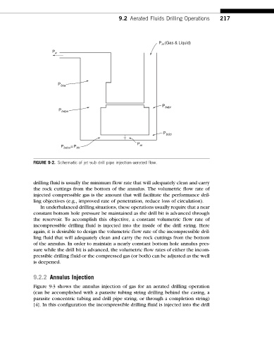
FIGURE 9-2. Schematic of jet sub drill pipe injection-aerated flow.
drilling fluid is usually the minimum flow rate that will adequately clean and carry
the rock cuttings from the bottom of the annulus. The volumetric flow rate of
injected compressible gas is the amount that will facilitate the performance dril-
ling objectives (e.g., improved rate of penetration, reduce loss of circulation).
In underbalanced drilling situations, these operations usually require that a near
constant bottom hole pressure be maintained as the drill bit is advanced through
the reservoir. To accomplish this objective, a constant volumetric flow rate of
incompressible drilling fluid is injected into the inside of the drill string. Here
again, it is desirable to design the volumetric flow rate of the incompressible dril-
ling fluid that will adequately clean and carry the rock cuttings from the bottom
of the annulus. In order to maintain a nearly constant bottom hole annulus pres-
sure while the drill bit is advanced, the volumetric flow rates of either the incom-
pressible drilling fluid or the compressed gas (or both) can be adjusted as the well
is deepened.
9.2.2 Annulus Injection
Figure 9-3 shows the annulus injection of gas for an aerated drilling operation
(can be accomplished with a parasite tubing string drilling behind the casing, a
parasite concentric tubing and drill pipe string, or through a completion string)
[4]. In this configuration the incompressible drilling fluid is injected into the drill