
Page 23 - Air and gas Drilling Field Guide 3rd Edition
P. 23
14 CHAPTER 2 Air and Gas Versus Mud
CROWN
BLOCK
MAST
“CROWS
NEST”
TRAVELING
AIR COMPRESSOR BLOCK
SWIVEL
HOSE
MUD PUMP
KELLY
HYDRAULIC
RESERVOIR
DOUBLE-DRUM
DRAW WORKS ROTARY
WITH SANDREEL
TABLE
CATHEAD
SUPPORT JACKS
DRILLER’S STATION
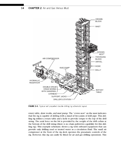
FIGURE 2-4. Typical self-propelled double drilling rig schematic layout.
rotary table, draw works, and mud pump. The “crows nest” on the mast indicates
that the rig is capable of drilling with a stand of two joints of drill pipe. This dril-
ling rig utilizes a rotary table and a kelly to provide torque to the top of the drill
string. The axial force on the bit is provided by the weight of the drill collars at
the bottom of the drill string (there is no chain pull-down capability for this dril-
ling rig). This example schematic shows a rig with onboard equipment that can
provide only drilling mud or treated water as a circulation fluid. The small air
compressor at the front of the rig deck operates the pneumatic controls of the
rig. However, this rig can easily be fitted for air and gas drilling operations. This