
Page 33 - Air and gas Drilling Field Guide 3rd Edition
P. 33
24 CHAPTER 2 Air and Gas Versus Mud
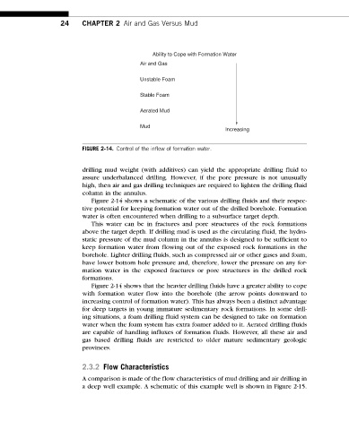
Ability to Cope with Formation Water
Air and Gas
Unstable Foam
Stable Foam
Aerated Mud
Mud
Increasing
FIGURE 2-14. Control of the inflow of formation water.
drilling mud weight (with additives) can yield the appropriate drilling fluid to
assure underbalanced drilling. However, if the pore pressure is not unusually
high, then air and gas drilling techniques are required to lighten the drilling fluid
column in the annulus.
Figure 2-14 shows a schematic of the various drilling fluids and their respec-
tive potential for keeping formation water out of the drilled borehole. Formation
water is often encountered when drilling to a subsurface target depth.
This water can be in fractures and pore structures of the rock formations
above the target depth. If drilling mud is used as the circulating fluid, the hydro-
static pressure of the mud column in the annulus is designed to be sufficient to
keep formation water from flowing out of the exposed rock formations in the
borehole. Lighter drilling fluids, such as compressed air or other gases and foam,
have lower bottom hole pressure and, therefore, lower the pressure on any for-
mation water in the exposed fractures or pore structures in the drilled rock
formations.
Figure 2-14 shows that the heavier drilling fluids have a greater ability to cope
with formation water flow into the borehole (the arrow points downward to
increasing control of formation water). This has always been a distinct advantage
for deep targets in young immature sedimentary rock formations. In some drill-
ing situations, a foam drilling fluid system can be designed to take on formation
water when the foam system has extra foamer added to it. Aerated drilling fluids
are capable of handling influxes of formation fluids. However, all these air and
gas based drilling fluids are restricted to older mature sedimentary geologic
provinces.
2.3.2 Flow Characteristics
A comparison is made of the flow characteristics of mud drilling and air drilling in
a deep well example. A schematic of this example well is shown in Figure 2-15.