
Page 114 - Aircraft Stuctures for Engineering Student
P. 114
98 Energy methods of structural analysis
€I
(a) (b)
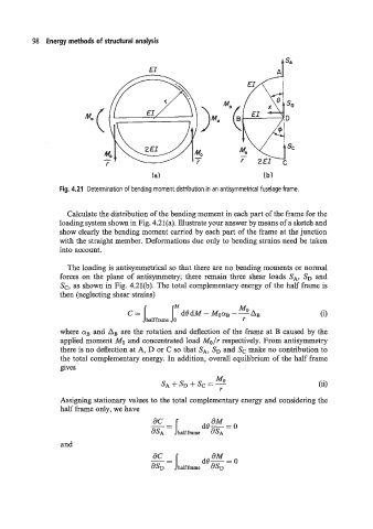
Fig. 4.21 Determination of bending moment distribution in an antisymmetrical fuselage frame.
Calculate the distribution of the bending moment in each part of the frame for the
loading system shown in Fig. 4.21(a). Illustrate your answer by means of a sketch and
show clearly the bending moment carried by each part of the frame at the junction
with the straight member. Deformations due only to bending strains need be taken
into account.
The loading is antisymmetrical so that there are no bending moments or normal
forces on the plane of antisymmetry; there remain three shear loads SA, SD and
Sc, as shown in Fig. 4.21(b). The total complementary energy of the half frame is
then (neglecting shear strains)
where aB and AB are the rotation and deflection of the frame at B caused by the
applied moment Mo and concentrated load Mo/r respectively. From antisymmetry
there is no deflection at A, D or C so that SA, S, and Sc make no contribution to
the total complementary energy. In addition, overall equilibrium of the half frame
gives
(ii)
Assigning stationary values to the total complementary energy and considering the
half frame only, we have
and