
Page 117 - Aircraft Stuctures for Engineering Student
P. 117
4.8 Unit load method 101
If instead of the arbitrary dummy load Pf we had placed a unit load at C, then the load
in the ith linearly elastic member would be
Therefore, the term dFi/6’Pf in Eq. (4.25) is equal to the load in the ith member due to
a unit load at C, and Eq. (4.25) may be written
(4.26)
where Fi,o is the force in the ith member due to the actual loading and Fi,l is the
force in the ith member due to a unit load placed at the position and in the direction
of the required deflection. Thus, in Example 4.2 columns @ and @in Table 4.1 would
be eliminated, leaving column @ as FB,l and column 0 as FD.l. Obviously column @
is Fo.
Similar expressions for deflection due to bending and torsion of linear structures
follow from the well-known relationships between bending and rotation and torsion
and rotation. Hence, for a member of length L and flexural and torsional rigidities EI
and GJ respectively
(4.27)
where Mo is the bending moment at any section produced by the actual loading and
MI is the bending moment at any section due to a unit load applied at the position and
in the direction of the required deflection. Similarly for torsion.
Generally, shear deflections of slender beams are ignored but may be calculated
when required for particular cases. Of greater interest in aircraft structures is the
calculation of the deflections produced by the large shear stresses experienced by
thin-walled sections. This problem is discussed in Chapter 9.
Example 4.8
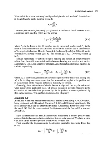
A steel rod of uniform circular cross-section is bent as shown in Fig. 4.23, AB and BC
being horizontal and CD vertical. The arms AB, BC and CD are of equal length. The
rod is encastrk at A and the other end D is free. A uniformly distributed load covers
the length BC. Find the components of the displacement of the free end D in terms of
EI and GJ.
Since the cross-sectional area A and modulus of elasticity E are not given we shall
assume that displacements due to axial distortion are to be ignored. We place, in turn,
unit loads in the assumed positive directions of the axes xyz.
First, consider the displacement in the direction parallel to the x axis. From Eqs
(4.27)