
Page 121 - Aircraft Stuctures for Engineering Student
P. 121
4.10 The reciprocal theorem 105
Finally we have:
The rotation at a point 1 due to a unit load at a point 2 is numerically equal to the
deflection at the point 2 in the direction of the unit load due to a unit moment at
the point 1.
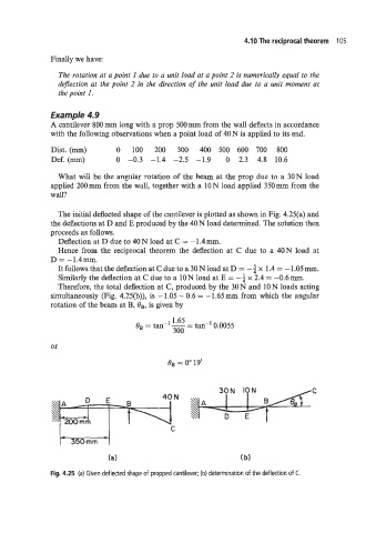
Example 4.9
A cantilever 800 mm long with a prop 500 mm from the wall deflects in accordance
with the following observations when a point load of 40 N is applied to its end.
Dist. (mm) 0 100 200 300 400 500 600 700 800
Def. (mm) 0 -0.3 -1.4 -2.5 -1.9 0 2.3 4.8 10.6
What will be the angular rotation of the beam at the prop due to a 30N load
applied 200mm from the wall, together with a 10N load applied 350mm from the
wall?
The initial deflected shape of the cantilever is plotted as shown in Fig. 4.25(a) and
the deflections at D and E produced by the 40 N load determined. The solution then
proceeds as follows.
Deflection at D due to 40N load at C = -1.4mm.
Hence from the reciprocal theorem the deflection at C due to a 40N load at
D = -1.4mm.
It follows that the deflection at C due to a 30 N load at D = - 2 x 1.4 = -1.05 mm.
f
Similarly the deflection at C due to a 10 N load at E = - x 2.4 = -0.6 mm.
Therefore, the total deflection at C, produced by the 30 N and 10 N loads acting
simultaneously (Fig. 4.25(b)), is - 1.05 - 0.6 = - 1.65 mm from which the angular
rotation of the beam at B, OB, is given by
1 1.65
OB = tan- - tan-' 0.0055
=
300
or
C
(a) (b)
Fig. 4.25 (a) Given deflected shape of propped cantilever; (b) determination of the deflection of C.