
Page 134 - Aircraft Stuctures for Engineering Student
P. 134
1 18 Energy methods of structural analysis
Fig. P.4.18
The frame is loaded in its own plane by a system of point loads P which are
balanced by a constant shear flow q around the outside. Determine the distribution
of the bending moment in the frame and sketch the bending moment diagram. In
the analysis take bending deformations only into account.
Am. Shears only at mid-points of vertical members. On the lower half of the
frame S4, = 0.27P to right, SS2 = 0.69P to left, = 1.08P to left; the bending
moment diagram follows.
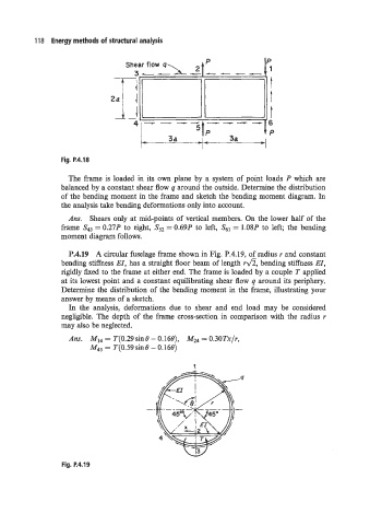
P.4.19 A circular fuselage frame shown in Fig. P.4.19, of radius r and constant
bending stiffness EI, has a straight floor beam of length rd, bending stiffness EI,
rigidly fixed to the frame at either end. The frame is loaded by a couple T applied
at its lowest point and a constant equilibrating shear flow q around its periphery.
Determine the distribution of the bending moment in the frame, illustrating your
answer by means of a sketch.
In the analysis, deformations due to shear and end load may be considered
negligible. The depth of the frame cross-section in comparison with the radius r
may also be neglected.
Am. MI4 = T(0.29 sine - 0.160), = 0.30Tx/r,
M4, = T(0.59sine - 0.166)
1
Fig. P.4.19