
Page 132 - Aircraft Stuctures for Engineering Student
P. 132
116 Energy methods of structural analysis
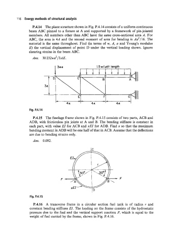
P.4.14 The plane structure shown in Fig. P.4.14 consists of a uniform continuous
beam ABC pinned to a fixture at A and supported by a framework of pin-jointed
members. All members other than ABC have the same cross-sectional area A. For
ABC, the area is 4A and the second moment of area for bending is A2/16. The
material is the same throughout. Find (in terms of w, A, a and Young’s modulus
E) the vertical displacement of point D under the vertical loading shown. Ignore
shearing strains in the beam ABC.
Am. 30232wa2/3AE.
1.5 whit length
lillill
0
Fig. P.4.14
P.4.15 The fuselage frame shown in Fig. P.4.15 consists of two parts, ACB and
ADB, with frictionless pin joints at A and B. The bending stiffness is constant in
each part, with value EI for ACB and xEI for ADB. Find x so that the maximum
bending moment in ADB will be one half of that in ACB. Assume that the deflections
are due to bending strains only.
Ans. 0.092.
Fig. P.4.15
P.4.16 A transverse frame in a circular section fuel tank is of radius r and
constant bending stiffness EI. The loading on the frame consists of the hydrostatic
pressure due to the fuel and the vertical support reaction P, which is equal to the
weight of fuel carried by the frame, shown in Fig. P.4.16.