
Page 133 - Aircraft Stuctures for Engineering Student
P. 133
Problems 117
t'
Fig. P.4.16
Taking into account only strains due to bending, calculate the distribution of
bending moment around the frame in terms of the force P, the frame radius r and
the angle 0.
-
Ans. M = Pr(0.160 - 0.080~0~0 0.1590sin0).
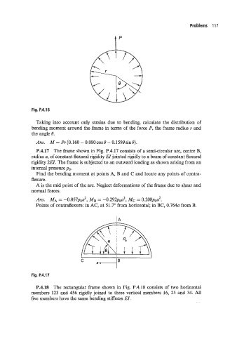
P.4.17 The frame shown in Fig. P.4.17 consists of a semi-circular arc, centre B,
radius a, of constant flexural rigidity EI jointed rigidly to a beam of constant flexural
rigidity 2EZ. The frame is subjected to an outward loading as shown arising from an
internal pressure po.
Find the bending moment at points A, B and C and locate any points of contra-
flexure.
A is the mid point of the arc. Neglect deformations of the frame due to shear and
noi-mal forces.
Ans. MA = -0.057pod, MB = -0.292poa2, Mc = 0.208poa2.
Points of contraflexure: in AC, at 51.7' from horizontal; in BC, 0.764~ from B.
Fig. P.4.17
P.4.18 The rectangular frame shown in Fig. P.4.18 consists of two horizontal
members 123 and 456 rigidly joined to three vertical members 16, 25 and 34. All
five members have the same bending stiffness EZ.